Hardware Reference
In-Depth Information
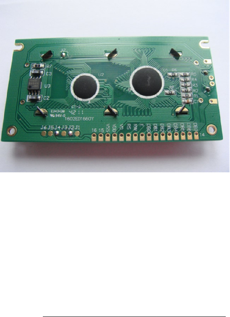
Figure 4-3.
The rear of my generic HD44780
Now place a probe on pin 15 and the anode pad. You will notice the multimeter reads zero, which means that the
two pins are connected to each other. If you try measuring from pin 16 to the anode you will notice that your meter
reads a large positive integer, which indicates they are not connected. Now that you have all the pins mapped out,
make a reference somewhere as you will need this information later on when you connect the jumper cables to the
LCD. If you're really lucky your handy data sheet will have all this information already for you.
Next up it's a good idea to understand what happens when you send an instruction to the LCD. Take a look at
Table
4-2
; you can see what the clear display instruction looks like in eight-bit mode.
Table 4-2.
The clear display instruction in eight-bit mode
Data Bus
DB7
DB6
DB5
DB4
DB3
DB2
DB1
DB0
Binary
0
0
0
0
0
0
0
1
Timing
200-ms wait
In this mode all eight data lines are used to send the one instruction, whereas in four-bit mode only the high four
data lines are used. The high data lines are DB4, DB5, DB6, and DB7. If you wanted to send the same clear display
instruction as above, you would now need to split the same eight-bit instruction into two separate sets of data with
timing in between. This is what makes the four-bit mode harder to program than the eight-bit mode. In Table
4-3
you
can see the exact same instruction but provided in the four-bit mode.