Biomedical Engineering Reference
In-Depth Information
D
t [ms]
Pulse width
Recharge cycle
1/3 A max
F
A
A max
A [V]
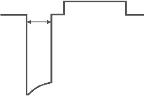
Fig. 8.5
Pulse amplitude and width measurement according to ISO
14708-2
Leading edge
Fig. 8.4
Output pacing pulse parameters
8.4
Adaptive-Rate Pacing
8.3.3.1 Pulse Amplitude
The pulse amplitude or output pulse voltage is measured as
the voltage of the leading edge of a device output pulse. The
amplitude is an independently programmable parameter, the
values of which can range from 0 (pacing is off) to 7.5 or
8.4 V or more, according to the type of device. Pacemakers
have a lower output capacity to improve the output signal
and are designed with circuits that recharge quickly upon the
discharging of an output coupling capacitor following a
paced pulse. This circuit ensures proper amplitude pulses at
higher rates and improves sensing circuit recovery after an
output pulse. Recharging the output circuit capacitor appears
on lead pacing electrodes as a low-amplitude pulse of oppo-
site polarity immediately after the output pacing pulse
(Fig.
8.4
).
Most up-to-date pacemakers are designed with a function
for automatic setting of the output pulse amplitude and mon-
itoring of the pacing efficiency. The purpose is to adapt pac-
ing pulses dynamically so that reliable pacing is ensured and
the output voltage is optimized simultaneously. The evalua-
tion of the successfulness of pacing is based on the resulting
electrogram (EGM). The EGM is sensed by either the
electrodes delivering the pacing or a special auxiliary sens-
ing electrode available in certain systems. Each algorithm
adds a certain safety reserve to the measured threshold,
though. If pacing is not delivered, the pacemaker applies a
back-up pacing pulse with a higher amplitude.
Pacing modes with an adaptive rate (frequency) are devised
for patients suffering from chronotropic incompetence who
would profit from the increased pacing rate during increased
activity. In the case of chronotropic incompetence, the physi-
ological increase of heart rate is insufficient. Various types of
failures may occur. In addition to being incapable of acceler-
ating the heart rate, it also insufficiently increases the heart
rate during activity, and decelerates the heart rate too quickly
after activity or various combinations.
Sensors are used to detect changes in a patient's metabolic
requirements. These are divided into three classes according
to the physiological level they sense. Primary sensors sense
physiological factors influencing a sinus node, for example,
circulating catecholamines, and the activity of the autono-
mous nervous system. Secondary sensors are capable of sens-
ing physiological parameters relating to physical activity, such
as minute ventilation (MV), temperature, muscle contractions,
or the QT interval. Tertiary sensors sense body motion as a
consequence of physical activity. Despite the number of sen-
sors, an ideal sensor capable of simulating the behavior of the
sinoatrial node is still not available. In practice, an accelerom-
eter is the most common sensor. Upon detection of increased
activity, the algorithm translates the measured level of activity
into the LRL increase above the basic value. For the purpose
of pacemaker timing, the algorithm thus sets a new higher
LRL. If all parameters are programmed properly, the pacing
increases with increasing activity and decreases if the activity
returns to the resting level.
The maximum value to which the pacing rate may increase
as a consequence of sensor driving is determined by a param-
eter that is named differently by different manufacturers: a
maximum sensor rate (MSR) or an upper sensor rate, or, in
the time domain, generally a sensor-driven interval. This
parameter is programmable, but usually not completely inde-
pendently. The parameters of adaptive-rate pacing are related
8.3.3.2 Pulse Width
The independently programmable parameter of pulse width
determines how long the output pacing amplitude will be
applied between pacing electrodes. The pulse width is pro-
grammable in the range of 0.05-2.00 ms. The pulse width is,
as per the standard [17], measured in one-third of the voltage
of the leading edge (Fig.
8.5
) .