Biomedical Engineering Reference
In-Depth Information
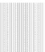
Fig. 8.3
Amplitudes and
frequency ranges of sensed
biosignals
[mV]
Input filters
transmission band
Ventricle
extrasystole
20
Input filters
frequency
characteristics
R-waves
15
Input filters
attenuation
band
10
T-waves
P-waves
5
Myopotentials
1
10
100
frequency [Hz]
1000
8.3.1
Sensing
T waves, noise, myopotentials, or external electromagnetic
interference; in inhibitory modes, it can lead to pacing inhi-
bition. Insufficiently sensitive sensing may cause redundant
and asynchronous or competitive pacing or pacing in the vul-
nerable phase.
Devices sense using lead sensing electrodes implanted in
heart chambers. The sensitivity of the intracardial signal
sensing is programmable, and the programmable value of the
sensitivity setting represents the threshold value, determin-
ing the minimum electric amplitude sensed by the device as
the intrinsic cardiac activity in the particular heart chamber.
Higher programmed values mean lower sensitivity to intrin-
sic electric cardiac activity and vice versa.
Today it is often possible to program automatic sensitivity
in each sensing channel. The device then automatically
adapts the sensitivity value to the level of a sensed signal by
means of automatic gain control system of the input amplifier.
The sensitivity level is updated in each cardiac cycle, and the
sensitivity range may differ for the atrium and the ventricle.
The level is set based on the average of the measured sensed
events and noise levels. For good functioning, a minimum
value of intrinsic signals - for example, a P wave of 1.0 mV
and an R wave of 5.0 mV - is recommended.
All devices in use today allow setting of modes with inhib-
ited “on demand” activity. Thus, in most pacing modes, the
device must sense the intrinsic cardiac activity in individual
heart chambers - efficient sensing is essential for its opera-
tion. Timing intervals (such as blanking and refractory peri-
ods) also help with proper sensing. During a blanking period,
sensing is completely inhibited; in refractory periods, sensed
events have no effect on the timing of pacing.
According to the lead polarity, sensing may be conducted
as bipolar or unipolar. Various pacing and sensing
configurations may be combined. In certain types of devices,
the sensitivity is also changed during a timing cycle in the
bipolar configuration to restrict T wave sensing. The set
sensing value is also applied in defibrillators for tachycardia
detection. Pacemaker detection circuits must have suitable
filter frequency characteristics so that sensing of electrical
processes in the body (other than cardiac activity), in particu-
lar myopotentials, is prevented. Frequency and amplitude
ranges of sensed biosignals are shown in Fig.
8.3
.
8.3.2
Sensitivity
8.3.3
Pacing Pulse
Sensing must be conducted at the appropriate sensitivity.
Sensitivity is defined as the lowest input signal waveform
amplitude at which device response is induced, that is, the
escape interval is triggered (see Chap.
9
). Per standards [ 17 ] ,
the sensitivity in the atrium and the ventricle is defined as the
amplitude of the standard test signal voltage, which is just
sufficient to be detected by the device. Laboratory measure-
ments of sensitivity are described in the standard. Today, the
field is well covered technically; in the past, however, inhibi-
tion characteristics were quite important in terms of practice.
Excessive sensitivity may cause sensing of far-field R waves,
A negative voltage pulse is needed for pacing. The amplitude
and width are optional parameters of the pacing pulse. It should
be noted that the total pacing energy is directly proportional to
the second power of the amplitude and the first power of the
pulse width according to the relationship
E = U
2
/(R*
T)
. During
manufacturing, the parameters of the pulse amplitude and
width are measured under standard conditions per the standard
[17]: 37 °C, rate 60 pulses/min, amplitude 3.5 V, pulse width
0.4 ms, and nominal sensitivity at three load values.