Graphics Programs Reference
In-Depth Information
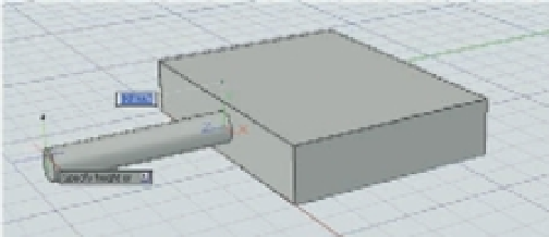
FIGURE 19.12
Drawing on the
side of a box
The face is highlighted.
The cursor's Z axis
is perpendicular to
the side of the box.
The UCS has always been an important tool for 3D modeling in AutoCAD. The example just
described demonstrates the Dynamic UCS, which automatically changes the orientation of the
X, Y, and Z axes to conform to the flat surface of a 3D object.
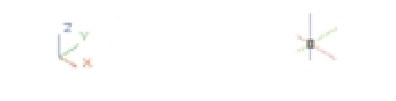
You may have noticed that when you created the new 3D file using the acad3D.dwt template,
the cursor looked different. Instead of the usual cross, you saw three intersecting lines. If you
look carefully, you'll see that each line of the cursor is a different color. In its default configura-
tion, AutoCAD shows a red line for the X axis, a green line for the Y axis, and a blue line for the
Z axis. This mimics the color scheme of the UCS icon, as shown in Figure 19.13.
FIGURE 19.13
The UCS icon at the
left and the cursor
in 3D to the right
are color matched.
Blue
Green
Red
As you work with the Dynamic UCS, you'll see that the orientation of these lines changes
when you point at a surface on a 3D object. The following exercise shows you how to use the
Dynamic UCS to help you rotate the box about the X axis:
1.
If you haven't done so already, click the disclosure triangle to the far right of the status
bar to expand the status bar.
2.
Be sure the Object Snap and Allow/Disallow Dynamic UCS features are turned on.
Allow/Disallow
Dynamic UCS
Object Snap