Environmental Engineering Reference
In-Depth Information
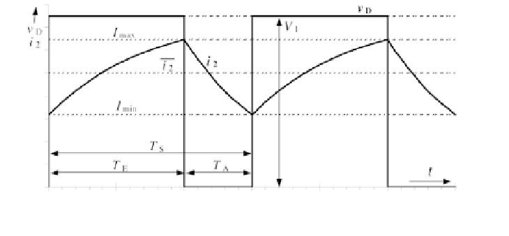
Figure 4.35
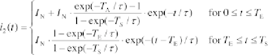
Current
i
2
and Voltage
v
D
for a Buck Converter
(4.75)
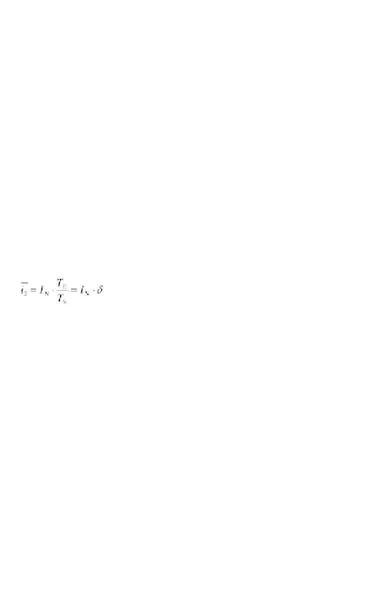
_
The average of the current
i
2
is:
(4.76)
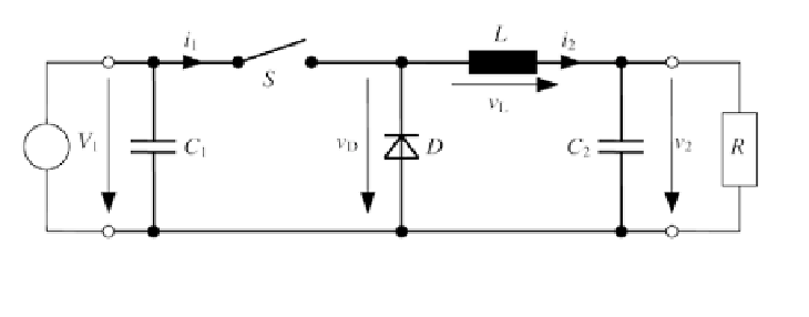
In practice, the output voltage should be relatively constant. Therefore, the
capacitors
C
1
and
C
2
shown in Figure 4.36 are inserted. Capacitor
C
1
buffers
the solar generator energy when the switch is open.
For an ideal inductance
L
, the mean output voltage is:
(4.77)
with the input voltage
V
1
and the duty cycle
δ
. Assuming ideal electronic
_
components, the mean output current
i
2
is given by:
Generator
Load
Figure 4.36
Buck Converter with Capacitors