Environmental Engineering Reference
In-Depth Information
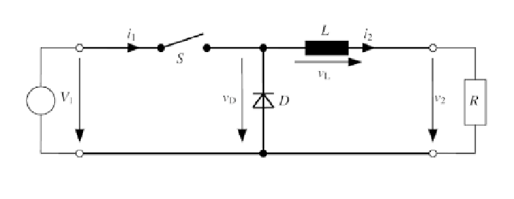
Generator
Load
Figure 4.34
Circuit of a Buck Converter with Resistive Load
(4.69)
The switch is then opened for a time period
T
A
and the magnetic field of the
inductance collapses and drives a current through the resistance
R
and the
diode
D
. When neglecting the forward voltage drop at the diode, the output
voltage
v
2
at the contacts becomes:
(4.70)
+
T
A
the procedure repeats. The mean voltage
_
After the period
T
S
=
T
E
D
with the
duty cycle
δ
=
T
E
/
T
S
is:
(4.71)
With
I
N
=
V
1
/
R
and
τ
=
L
/
R
, the current
i
2
through inductance and load
becomes:
(4.72)
The current
i
2
is between the maximum current (Equation 4.73) and the
minimum current (Equation 4.74):
(4.73)
The minimum current is:
(4.74)
Using
I
min
and
I
max
leads to the current
i
2
(Michel, 1992):