Hardware Reference
In-Depth Information
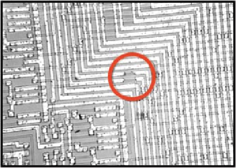
Fig. 8.2
Example of open defects in the application circuit
“non significant” for test purposes because such faults can be easily revealed by any
test sequence. Figure
8.2
illustrates opens affecting two metallization lines in the
Timing Unit.
Two alternative approaches have been followed to cope with defects that cannot
be handled by logical fault models:
1.
Try to
generate test sequences
accounting directly for the defects (shorts and
opens) at the electrical level.
2.
Propose
restrictive layout rules
, so that defects results essentially to stuck-at
faults at the logic level.
8.2.2
Generation of Test Sequences for Shorts and Opens
8.2.2.1
Basic Consequences from the Failure Mode Analysis
Concerning test sequence generation and fault simulation, the results of the failure
mode analysis have two very important consequences.
Not All Defects Can Be Modeled by Stuck-at Faults
This can be clearly illus-
MOS gate on which two possible shorts (#1 and #2) and two possible opens (#3 and
#4) are indicated. Short #1 and open #3 can be modeled by a stuck-at-1 at input e
and by a stuck-at-0 at input e (or input f or both), respectively. On the other hand,
short #2 and open #4 cannot be modeled by any stuck-at-fault because they lead to
a modification of the function realized by the gate. For the same reason, a short be-
Representing the Circuit as a Logic Diagram Is Not Adequate
Taking into ac-
count physical defects such as shorts and opens implies the consideration of the
actual topology of the circuit. This advocates for the consideration of an electrical