Hardware Reference
In-Depth Information
a
b
V
DD
V
DD
S
1
S
2
Load
transistor
a
c
a
b
e
1
Switch-like
network
b
d
4
2
V
SS
c
d
f
Without short: S
1
= a.b S
2
= c.d
With short: S
1
= S
2
= a.b+c.d
3
V
SS
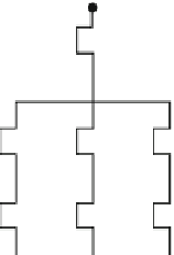
Fig. 8.3
(
a
) Failure examples in a MOS gate. (
b
) Short between the outputs of two gates
V
DD
s
a
b
?
a
b
e
?
2
c
d
?
?
?
1
s
c
d
f
?
e
f
?
V
SS
Electrical diagram
Logic diagram
Fig. 8.4
Relations between electrical and logic diagrams
diagram rather than a logic diagram, since the latter does not constitute a real model
of the physical circuit. Some connections of the real circuit are not represented in
the logic diagram, whereas some connections appearing on the logic diagram may
be missing in the physical circuit.
As an example, Fig.
8.4
shows the logic and electrical diagrams of the same gate.
The faults considered in each diagram are those that cannot be represented on the
other or even cannot occur.
For instance, short #2, which is physically possible, cannot be represented on the
logic diagram, and short #1 in the logic diagram has no physical meaning.
Consequently, all methods for test sequence generation and fault simulation
based on a stuck-at fault model at the logic diagram level are not well adapted.
A possible approach for fault simulation may be to introduce short defects or, bet-
ter, to work directly with the transistor diagram. For test sequence generation, it is
necessary to use a new method accounting directly for the faults at the gate and
blocks levels.