Geology Reference
In-Depth Information
Interacting Thrust
Fault Array
200 m
4
3
2
fault tips curve
toward each other
1
A
8
7
6
summed
displacement
5
propagation
4
barrier?
3
4
2
3
2
1
1
0
0
200
400
600
800
1000
1200
1400
B
Distance (m)
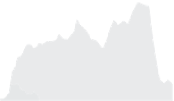
Fig. 4.27
Array of interacting thrust faults.
A. Fault traces of four small thrust faults that cut a late-glacial outwash surface in the Ostler Fault zone, South Island,
New Zealand. The curvature of the fault tips is similar to elastic crack behavior observed on scales from millimeters
in rock fracture experiments to scales of kilometers on mid-ocean ridge segments and inferred to result from
out-of-plane crack interactions (Sempere and Macdonald, 1986). B. Along-strike displacement for individual faults.
The summed displacement illustrates compensation between overlapping fault tips and shows a consistent taper
toward the north. The abrupt termination to the south suggests the presence of a barrier to fault propagation, as in
Fig. 4.10 D. Modified after Davis
et al.
(2005).
strike-slip faults. Nonetheless, where arrays of
thrusts do cut the surface, they display the same
types of compensatory, interacting patterns
(Figs 4.15 and 4.27) as previously described for
normal faults.
Geodetic measurements of coseismic defor-
mation (Stein
et al.
, 1988) indicate that, during
thrusting, hanging-wall uplift is typically con-
siderably greater than footwall subsidence
(Fig. 4.28). This pattern is the mirror image of
the coseismic deformation associated with many
normal faults (Fig. 4.25). The area affected by
the coseismic deformation depends on the
magnitude of displacement, the geometry of
faulting, and the rigidity of the crust that is
being deformed. In the 1952 Kern County
earthquake in southern California, deforma-
tion extended for about 40 km on either side
of the rupture (Fig. 4.28). Although the total
vertical offset in this earthquake (
Thrust faults
Thrusts faults develop where the maximum
compressive stress (
s
1
) is horizontal and a
vertically oriented deviatoric tensile stress exists
(Fig. 4.1B). In theory, thrusts should cut a
horizontal land surface at about 30
°
angles, but,
in fact, thrusts and reverse faults can cut the
surface at any angle and may occasionally be
overturned at the surface. Owing to the
commonly low-angle intersection of thrust faults
with the Earth's surface, however, the traces of
thrusts are more strongly affected by topography,
such that they tend to be more highly sinuous
than are normal faults, rendering it more diffi-
cult to measure offsets if the direction of fault
motion is not well defined. Many thrust faults
are “blind” and do not cut the surface, such that
their displacement characteristics are more
difficult to define than for many normal or
∼
100 cm) was