Civil Engineering Reference
In-Depth Information
6.1.3
Construction materials
6.1.3.1 Concrete compressive strength
Concrete of class B35 was able to be ascertained from the as-built documents
according to DIN 1045 [94]. Following a test on the member, the result was strength
class C30/37. Therefore, the values according to DIN EN 1992-1-1 [20] Tab. 3.1 for
C30/37 concrete will be used for the design. This results in a mean concrete
compressive strength
f
cm
=
38 N/mm
2
and a characteristic concrete compressive
30 N/mm
2
.
strength
f
ck
=
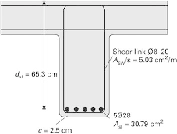
6.1.3.2 Type and quantity of existing reinforcement
According to the as-built documents, the longitudinal reinforcement is
ve Ø28mm
ribbed steel reinforcing bars (
A
sl
=
30.79 cm
2
) and shear reinforcement in the form of
vertical Ø8mm links @ 200mm c/c (
A
sw
/
s
=
5.03 cm
2
). It is apparent from the
documents that the reinforcing steel is grade BSt 500 S (IV S) to [94] or [97].
Consequently, we can assume a yield stress
f
syk
=
500 N/mm
2
and a modulus of
elasticity
E
s
=
200 kN/mm
2
.
6.1.3.3 Position of existing reinforcement
The as-built documents indicate a concrete cover of min
c
=
2.0 cm, or nom
c
=
3.0 cm,
according to DIN 1045 [94]. A survey according to [98] has revealed that
the
reinforcement is positioned as shown in Figure 6.3.
6.1.3.4 Strengthening system
Commercially available CFRP strips with a characteristic tensile strength
f
Luk
=
2400 N/
mm
2
and modulus of elasticity
E
L
=
170 kN/mm
2
are to be bonded in slots for the
strengthening. Strips with dimensions of (
t
L
×
b
L
)20
2mm are to be used. The system
includes an appropriate epoxy resin adhesive, for which a tensile strength
f
Gtk
=
×
30 N/
mm
2
and a compressive strength
f
Gck
=
90 N/mm
2
will be assumed in the design. The
other coefficients specific to this system are
k
sys
=
0.8,
k
bck
=
2.5,
α
bc
=
0.9 and
α
bG
=
0.5.
Fig. 6.3
Type and position of existing reinforcement.(other reinforcement omitted for clarity)

Search WWH ::

Custom Search