Information Technology Reference
In-Depth Information
Next, we consider the combined effect of spin-wave packets produced by two
input devices. We assume that each of the input devices generates a spin-wave
packet, which is described by Equation 7.3. The amplitudes of the input signals are
the same, while the relative phase between the signals can be controlled, for
example, by the polarity of the applied current pulses. The current pulses having
the same polarity produce local magnetic fields oriented in the same direction, so
the generated spin-wave packets have the same initial phase (
f
1
=
f
2
). In the
other case, when the current pulses have different polarity, the produced spin-
wave packets have relative phase difference. (
f
1
=
f
2
=
p
)
In order to find the magnetization change caused by two spin-wave packets,
we calculated the resultant magnetization as a superposition of waves of the same
frequency from each packet.
Z
w
=
2
Z
h
i
d
o
dy
1
w
M
y
¼
M
1y
ðoÞþ
M
2y
ðoÞþ
2M
1y
ðoÞ
M
2y
ðoÞ
cos
ðf
1
f
2
Þ
ð
7
:
5
Þ
o
w
=
2
In above equation, w is the width of the detecting device along the Y axis (the gap
between the strips), and the subscripts depict the magnetization components of the
first and the second packets, respectively. We made integration over the finite
length (w=200 nm) to take into account the effect of dephasing. Then, we
calculated the inductive voltage according to [1]:
d M
y
dt
m
0
ldf
ð
z
;
w
Þ
Z
Z
þ
0
V
ind
¼
;
ð
7
:
6
Þ
4
:
5R
dc
where
m
0
is the magnetic constant, l is the length of the sample, f(z,w) is the spacing
loss function, Z is the strip line resistance, and R
dc
is the total ACPS line
Relative phase (
1
−
2
) =
0
30
20
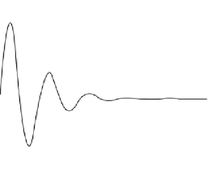
Relative phase (
1
−
2
) =
10
0
−
10
−
20
0
1
Time (ns)
2
Figure
7.18.
Numerical simulations results: output of two spin-wave packets.


Search WWH ::

Custom Search