Hardware Reference
In-Depth Information
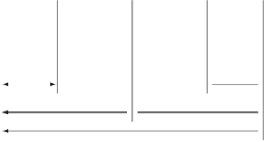
PP0Lx = 0
PP0Lx = 1
PWMDTYx
PWMDTYx
PWMPERx
PWMPERx
Period = PWMPERx * 2
Figure 8.48
■
PWM center-aligned output waveform
Clock source 7
High
Low
PWMCNT6
PWMCNT7
Period/Duty compare
PWM7
Clock source 5
Low
High
PWMCNT5
PWMCNT4
Period/Duty compare
PWM5
Clock source 3
High
Low
PWMCNT2
PWMCNT3
PWM3
Period/Duty compare
Clock source 1
High
Low
PWMCNT1
PWMCNT0
Period/Duty compare
PWM1
Figure 8.49
■
PWM 16-bit mode
When PWM channels
k
and
k
1 1 are concatenated, channel
k
is the high-order channel,
whereas channel
k
1 1 is the low-order channel. When using the 16-bit concatenated mode, the
clock source is determined by the low-order 8-bit channel clock select control bits. That is, it is
determined by channel
k
1 1 (
k
5 0, 2, 4, or 6) when channel
k
and
k
1 1 are concatenated. The
resulting PWM is output to the pin of the corresponding low-order 8-bit channel. The polarity


Search WWH ::

Custom Search