Hardware Reference
In-Depth Information
PLLSEL or SCM
wait (CWAI,SYSWAI)
stop
PLLCLK
1
Phase-
lock
loop
SYSCLK
Core
clock
0
wait,
stop
Clock
phase
generator
÷
2
E-clock
wait(RTIWAI),
stop(PSTP, PRE)
RTI enable
SCM
1
EXTAL
RTI
OSCCLK
Oscillator
0
wait(COPWAI),
XTAL
stop(PSTP, PCE)
COP enable
Clock
monitor
COP
wait(SYSWAI),
stop
Oscillator
clock
Gating
condition
stop(PSTP)
Oscillator
clock (pseudo-
stop mode)
= Clock gate
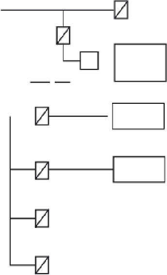
Figure 6.15
■
HCS12 clock generation circuit
Example 6.2
▼
There is a system that derives its E-clock from the PLL circuit, and an external clock of
8 MHz is selected. The desired E-clock is 24 MHz. Write an instruction sequence to perform the
desired configuration.
Solution:
Since the E-clock frequency is higher than the external clock's, we need to use the PLL
circuit. According to Figure 6.15, the frequency of SYSCLK would be 48 MHz. The frequencies
of OSCCLK and PLLCLK are 8 MHz and 48 MHz, respectively. According to Equation 6.1,
48 MHz
5
2
3
8 MHz
3
[SYNR
1
1]/[REFDV
1
1]
One of the alternatives could be to set SYNR and REFDV to 2 and 0, respectively. The following
subroutine achieves the desired configuration:
SetClk8
movb
#$02,SYNR
; set SYNR to 2
movb
#$0,REFDV
; set REFDV to 0
movb
#$80,CLKSEL
; enable PLL, keep SYSCLK running in wait mode,
; keep RTI, COP, PLL, and core running in wait mode


Search WWH ::

Custom Search