Environmental Engineering Reference
In-Depth Information
of natural rock with no visible support elements.
Rock surfaces with half-barrels after blasting,
anchors, bolts, steel mesh or shotcrete will not
be acceptable finish. Thus, it will be necessary to
apply some special treatments and surface finish-
ing techniques. These methods are the following:
- The excavation in all the space (cavern, light
shafts and entrance tunnel) will leave a skin
rock, at least 50 mm thick, between the excava-
tion and finished roofs and walls. This will sub-
sequently be cut off using a diamond wire to
create a smooth finished rock surface.
- all the permanent support (bolts and anchors)
will be countersunk with holes to a depth below
the finished surface to prevent being cut by the
diamond wire.
- The rock bolt and anchor holes will be reamed
with a thin-walled core barrel and the rock cores
will be retained.
- The threaded ends of the rock bolts will be used
to hold pulleys around which the diamond wires
will run.
- Discs of rock will be cut from the retained rock
cores and cemented into the reamed sections of
the rock bolt and anchor holes using a suitable
rock adhesive.
- The cavern and entrance tunnel loors will be
ground.
- Weathered dykes will be cut back, drained and
supported with a shotcrete or concrete infill.
- Discontinuities containing seasonal and long
term ground water flows will intersect the light
shafts and cavern walls. Drainage pipes will
not be permitted and the inflows and seepages
will need to be intersected and fully sealed with
grout.
- Finally, the cavern walls and roof will be cleaned
with high pressure water jets and geotextile will
be fixed to the finished surfaces and sprayed
with a resin coat. The geotextile and resin will
be used to secure the rock surfaces between the
anchors and rock bolts (steal mesh or shotcrete
are not aesthetically acceptable). if resin and
geotextile are not sufficient to support the little
blocks of rock, additional small (1 m long) rock
bolts (stainless steels pins) will be installed and
cement grouted. it is possible that resin and geo-
textile will not be required in the walls of the
space.
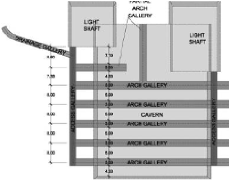
Figure 12.
Plan view of galleries above roof cavern.
subsequently, will be excavated the arch galleries
(3 m wide and 3.5 m high) between the access
galleries. a partial arch gallery will be also exca-
vated between the light shafts. all the muck will
be cleared through the pilot shafts to the pilot
gallery. a drainage gallery (2 m wide and 3 m
high) will be excavated from the mountain slope
- The support in the arch galleries will be installed
and operative before excavation of the cavern
roof starts.
- The cavern roof will be excavated as a series of
parallel headings from the light shafts and rock
bolts and anchors will be installed as the head-
ings are advanced.
- The remaining cavern volume will be excavated
as a series of benches and the constructor will
choose to simply remove the rock as spoil or
recover blocks for commercial use.
- The entrance tunnel will be excavated to full size
from the cavern to the portal.
explosives will not be permitted in the portals
areas (entrance tunnel and light shafts) to avoid
damage to the mountain slopes. The portal of
the entrance tunnel will be the unique access to
the works in the space in order to reduce envi-
ronmental problems in the mountain. although
mechanical excavation will be used in portals, the
underground works will be excavated using drill
and blasting techniques.
7
MoniToRinG
6
sPecial TReaTMenTs anD sURFace
FinishinG
The galleries above the cavern roof will remain
open to provide permanent access to the cavern
support and instrumentation points. The instru-
mentation will monitor the rock mass and ground
The artistic concept of chillida´s sculpture will
require that all the inner faces of the space will be