Environmental Engineering Reference
In-Depth Information
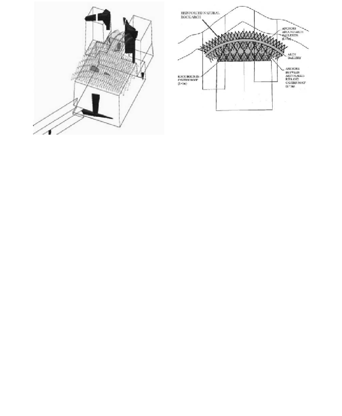
Figure 11.
Roof cavern support concept.
Figure 10.
3Dec result print.
surfaces. if unrestrained, the release surfaces will
relax into shafts, reducing the shear strength along
these surfaces. This effect becomes worse by non-
circular shaft profiles.
The support solution in light shafts consists of
10 m long anchors with working loads of 76 t and
rock bolts of 7 m length and working load of 30 t.
The entrance tunnel will be supported with 7 m
long rock bolts.
4.5
Cavern permanent support
The solution for the roof cavern permanent sup-
port consists of curved arch galleries above the
cavern roof from which anchor radiate to obtain a
reinforced rock arch within the ground (
Figure 11
).
The complete cavern permanent support includes:
- 7 m long anchors forming the arches radiate
around the galleries, such that the galleries are situ-
ated within an annular arch of strengthened rock.
- 14 m long anchors supporting the ground
between the arches and cavern roof.
- Rock bolts of 3 m in length installed from the
roof of the cavern during its excavation to sup-
port little blocks.
- Rock bolts of 7 m in length installed from the
walls of the cavern.
- The rock pillar between the two light shafts will be
supportedabovethecavernroofwithsub-horizontal
stranded ground anchors (l = 23 m). addition-
ally radiating bolts will be installed from a gallery
extending into the pillar from the rock arches to
support the pillar above these ground anchors.
The maximum working axial load required for
anchors is 88 t in the area between the arch galler-
ies and cavern roof. in the sub-horizontal anchors
between the light shafts the maximum working axial
load is 60 t. The load of rock bolts in cavern roof
and anchors around the arch galleries was of 30 t.
5
consTRUcTion MeThoD
Basically, the construction sequence of the space
is the following:
- construction of portal and pilot gallery of
entrance tunnel.
- Pilot gallery will bifurcate to the base of each
light shaft and pilot shafts will be excavated
upwards (“raised”) from the pilot gallery to
ground surface using an alimak system. Pilot
gallery and pilot shafts will be supported with
temporary fibreglass rock bolts and, if it is nec-
essary, shotcrete. a third alimak shaft could be
excavated for safety reasons.
- a test gallery will be excavated of the pilot gal-
lery and within the future space of the cavern to
prove excavation, support and surface finishing
techniques and to perform in situ and labora-
tory tests.
- excavation of the complete section of light
shafts from the ground surface.
- Two access galleries (2.5 m wide and 3 m high)
will be excavated from the light shafts when
the light shafts floors reach the galleries level.
4.6
Light Shafts and entrance tunnel permanent
support
The joints are predominantly subvertical, such
they form rock columns bounded by joint release