Environmental Engineering Reference
In-Depth Information
Figure 5. Typical cross section removed from the base
of the hillside.
in situations where embankments required retain-
ing structures higher than 3.0 meters the solution
selected was reinforced soil walls (M08 and M14)
or reinforced concrete walls (M10) with Ø1000 mil-
limeter diameter jet-grouting piles normally running
through to the bed rock. in particular, reinforced
earth retaining walls are characterized as being
highly resistant to static and seismic soil movements
and capable of adapting to unfavorable founda-
tions, thus being considered a suitable solution for
the specific conditions expected.
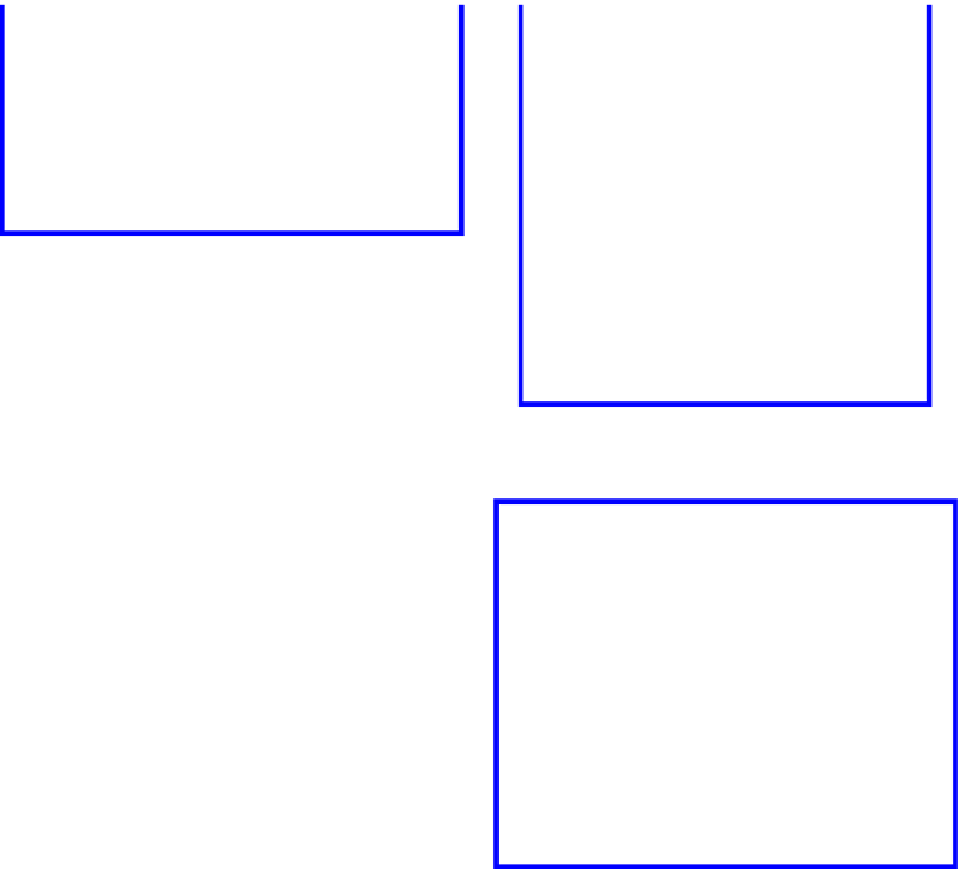
This type of structure, which the cross section is
shown in Figure 6, has the additional advantage of
being quick and easy to build at a fairly competi-
tive cost and blending well with the surroundings.
Where the situation required excavating slope
deposits to a depth of more than 3.0 meters and
where the rock mass was located at an elevation
below the road bed the solution selected was an
anchored pile wall with Ø800 millimeter piles set
with 1 or 2 levels of permanent anchors with load
capacities between 480 kn and 720 kn.
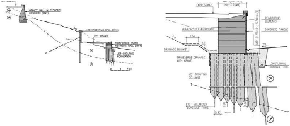
The primary objective of using this type of
retaining structure (M08, M15 and M16), of which
a cross section can be seen in Figure 7, is to control
the deformation of soil behind the structure and
consequently deformations in buildings located
oftentimes very close to the top of the structure.
This solution is also quick and easy to build.
The concrete piles were placed at a distance of
1.20 meters from each other, running from the nat-
ural surface of the terrain, in most cases into the
rock mass to a depth of no less than 3 times the
diameter of the pile. however, in locations where
the slope deposits at the level of the pile penetra-
tion depth were deeper than about 6.0 meters, a
decision was made not to drive all of the piles into
the rock mass but instead to use a solution of alter-
nating suspended and deep piles, thus optimizing
costs. altogether the walls projected include piles
varying in length from 5.0 meters to 20.0 meters.
The solution selected for containing excavated
slopes in the volcanic formations was soil nailing
Figure 6. Reinforced earth retaining walls with jet-
grouting foundation.
Figure 7.
anchored pile wall.
structures made of shotcrete and soil nails defined
as required by the nature and mechanical charac-
teristics of the formations to be excavated, comply-
ing with the behavior observed in natural slopes of
similar characteristics.
This solution enables not only a sufficient sheath
to confine and avoid the progressive erosion of the
slopes, but also provides a light weight, flexible and
low cost coating associated with the ground and
that takes advantage of its resistance.
in general two types of walls were considered:
Type “a” walls, denser and more resistant, to be
used in the more weathered formations or those
that are more easily broken down, made up of
two layers of shotcrete not less than 5 centimeters
thick, each one around an electro-welded mesh
such as aQ50, and lighter type “b” walls, used
for slopes in more compact formations, made up