Environmental Engineering Reference
In-Depth Information
shallower slope deposits capable of being removal,
the option was made for gravity walls in cyclo-
pean concrete supported directly on the rock bed,
thus keeping wall deformation and consequently
embankment and road bed deformation at a mini-
mum. such structures offer the additional advan-
tage in that they are quickly and easily built and
their cost is lower than other structures of a similar
height, such as reinforced concrete walls. This solu-
tion was generally used for expressway structures,
since the route alignment runs along the base of
rocky cliffs where slope deposits are shallower,
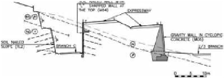
as can be seen in the cross section shown in Fig-
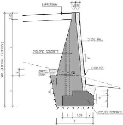
ure 2. The height of this set of walls (M03, M05,
M12 e M22) (type and cross section can be seen in
Figure 3
)
varies between 4.0 and 12.0 meters.
Where it was necessary to make deep excavations
into the rock face and because of the geometry of
the route, required an inclination close to the verti-
cal, soil nailed walls were placed in order to protect
and stabilize the excavation. This is a fast, flexible
and low cost solution that takes advantage of the
resistance of the rock mass itself.
in locations where nailed walls were to be build
and where the road bed was at an elevation above
the top of the massif with a maximum difference
in elevation of around 3.0 meters, a reinforced con-
crete wall (l-shaped cross-section) was placed at
the top of the nailed walls to support the embank-
ments required to retain the road bed. This solu-
tion was only required in excavations associated
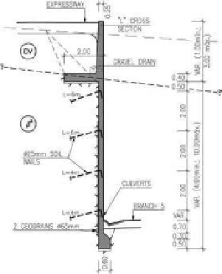
soil nailed walls (M01, M02, M04) with a
l-shaped section as shown in Figure 4 are made
up of a 0.25 meter thick reinforced concrete wall
poured directly onto the excavations face with
heights varying between 4.0 and 10.0 meters and
with 1 to 4 levels of nails using 4.0 to 6.0 meter
long, 25 mm diameter steel rods.
in situations where excavations of more than
3.0 meters were required in slope deposits and
where, on the one hand, the massif was located at
about the same elevation as the road bed and, on the
other, there were space limitations due to the prox-
imity to buildings at the top of the excavation, an
anchored wall solution was employed so as to con-
trol and limit deformations. The only anchored wall
included (M13) has a maximum height of 4.2 meters
and is made up of 2 rows of reinforced concrete
panels and 1 level of 480 kn capacity anchors.
The various branch roads are placed at eleva-
tions lower than the expressway as slope deposits
are quite a bit deeper making them impossible to
be completely removed so as to develop suitable
conditions for placing the foundations of the dif-
ferent retaining structures. Thus the structures
built in these locations required deep foundations
as illustrated in Figure 5.
Figure 2.
Typical cross section next to the base of the
slope.
Figure 3.
Gravity walls in cyclopean concrete.
Figure 4.
soil nailed walls with a l-shaped section wall
at the top.
3.1
Machico Sul Interchange
Where it was necessary to build retaining structures
for road bed embankments located in areas with