Environmental Engineering Reference
In-Depth Information
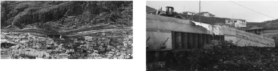
Figure 8.
overview of the Machico sul interchange.
Figure 9. overview of M6 wall in the start of
construction.
of one layer of shotcrete not less than 5 centim-
eters thick sprayed onto an electro-welded mesh
type cQ30.
soil nails are made of a400nR steel rods
25 or 32 millimeters in diameter, sealed into 3″
(0.076 millimeter) holes with cement slurry. Rods
vary in length based on the geological-geotechnical
characteristics and the geometry of each group of
slopes to be stabilized.
it should be noted that only one excavated slope,
in its more weathered and disaggregated areas, was
treated. This slope is about 760 meters long and
as high as 20 meters. Figure 8 shows a view of the
construction and the entire length of this excava-
tion slope (Tl2).
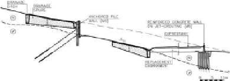
Figure 10. Typical cross section for the stretch follow-
ing the Portais Tunnel.
vals driven from the surface of the natural terrain
(
Fig. 9
). Their free height varied between 3.5 meters
and 6.5 meters. one or two levels of permanent
anchors were included, with load capacities of 600
and 720 kn and 35° from horizontal, to be built
whenever pilings, with 20.0 and 28.0 meters long,
as it can be seen at Figure 10.
along the wall, where the rock mass is located
at elevations significantly lower than the bottom of
the excavation, it was necessary to improve ground
properties in order to ensure an adequate behavior
of the structure, in particular its ability to mobilize
the passive resistance. Thus, given that jet-grouting
technology was available on site, slope deposits
were treated using this technology along a stretch
some 30 meters long and 4.0 meters wide, con-
structing jet-grouting pilings driven down into the
rock mass. Jet-grouting treatment used Ø1000 mil-
limeter diameter columns set in a 1.0 meter (longi-
tudinal to the wall) × 7.0 meter (transverse to the
wall) grid.
Two areas of the soil mass, each about 2.0 meters,
were left untreated at the base of the treated
area so as not to avoid natural percolation in the
soil which could raise the groundwater level behind
the wall.
Given the importance of water to the resist-
ance of this formations, and because the retaining
structure was designed taking into consideration
soil drainage behind the structure, a suitable drain-
age system was designed to effectively lower the
groundwater level in the area. Thus, in addition to
3.2
Caniçal interchange/Caniçal roundabout
immediately after the east exit of the Portais
Tunnel, the expressway runs along an area of
slope deposits of significant depth, at times up
to 10.0 meters. These deposits show evidence that
they are evolving as buildings located in the village
of Machico, close to the area where construction
occur, show signs of significant damage that can
be attributed to movement in this mass of slope
deposits.
For this reason, in addition to ensuring the sta-
bility of the retaining structures developed to build
the highway, an attempt was made to substantially
improve the overall stability of the mass of existing
slope deposits, thus minimizing future damage to
these buildings.
Therefore the solution found was to build
the retaining structure (M6 wall) away from the
expressway, thus reducing the slope deposits to be
supported and the mass potentially instable by the
partial removal of it. Because of the depth of the
deposits in this area it was impossible to support
the retaining structures by shallow foundations
making necessary the use of deep foundations.
With an excavation deeper than 3.0 meters into
slope deposits, an anchored pile wall was defined,
with 1 or 2 levels of anchors made of Ø800 rein-
forced concrete pilings placed at 1.0 meter inter-