Hardware Reference
In-Depth Information
3.
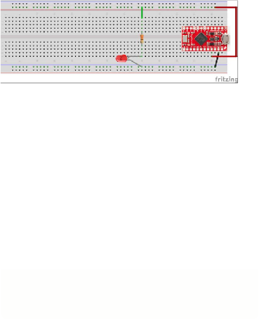
So that you can test the LED first, run a wire from the resistor leg on the top half
of the breadboard to the positive power rail at the top of the breadboard. You will
move this a little later.
FIGURE.5-7
An LED and a resistor wired to an Arduino
The instructions for the Raspberry Pi and the PC/Mac (using the Arduino) differ here a
bit, so work through the section that is relevant to the board you are using.
On the Raspberry Pi:
1.
If you have a sticky label in your kit for the Pi-T-Cobbler, stick it on so it looks
like Figure 5-8. This will help you to find the correct GPIO pins more easily.
Attach the Pi-T-Cobbler to the breadboard so that the black connector is on the
right hand just hanging of the edge of the breadboard. Push it into the right
hand side of the breadboard so that it lines up with the holes on the far right
hand edge of the breadboard. Half of the pins should push into the top half of
the breadboard, and half of the pins should push into the bottom half of the
breadboard. Push quite hard to make sure it goes all the way in.
2.
Connect the ribbon cable between the Pi-T-Cobbler and the Raspberry Pi. There
is a notch in the socket and a slot in the plug of the Pi-T-Cobbler that means it
will only go in one way. When you connect the ribbon cable to the Raspberry Pi,
make sure that the plastic lug on the connector faces away from the edge of the
Raspberry Pi circuit board; otherwise all the pins will be connected the wrong
way and it won't work! Figure 5-8 shows what this looks like.
The last thing to do is to check that your computer can turn the LED on. Before
flashing it with a Python program, you will first test out the LED by using power
provided by your computer.