Hardware Reference
In-Depth Information
3.
Run a wire between the positive power rail at the top of the breadboard and the
pin on the Pi-T-Cobbler labelled as 3V3.
4.
Run a wire between the negative power rail at the bottom of the breadboard and
the pin on the Pi-T-Cobbler labelled as 0V.
Provided your Raspberry Pi is powered up, your LED should now light up, as it is being
powered by the power supply of your computer.
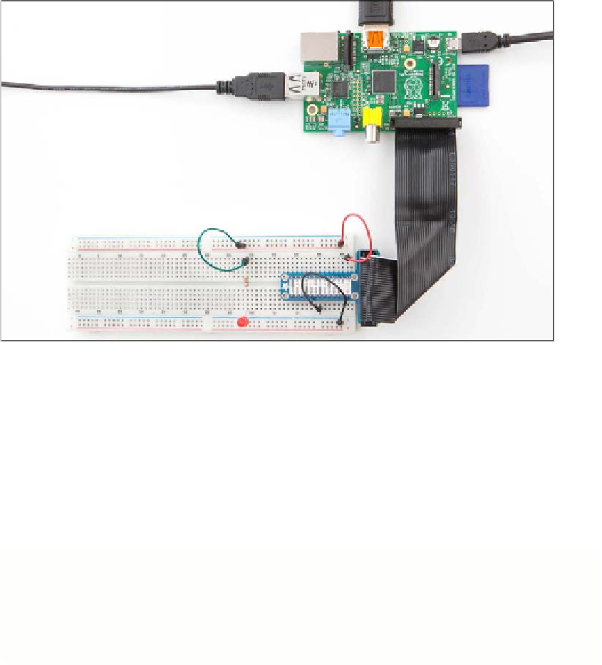
FIGURE.5-8
The Pi-T-Cobbler connected to the Raspberry Pi
On the Arduino:
1.
Line the Arduino up on the right-hand edge of the breadboard so that the silver
USB socket hangs off the right-hand edge. You might have to push quite hard to
get the pins to push into the breadboard, but put even pressure across the whole
circuit board so that it doesn't break. Figure 5-9 shows what this looks like.
2.
Connect the USB lead from your computer to the Arduino.
The last thing to do is to check that your computer can turn the LED on. Before
flashing it with a Python program, you will first test the LED out by using power
provided by your computer.