Hardware Reference
In-Depth Information
onscreen, this program flashes an LED. If you can program the computer to flash a
single LED when everything is set up, then you know that everything is working and
you can expand to bigger and more exciting projects.
This is going to be a special LED, though, because it will be linked to the Minecraft game.
You are going to extend an idea that you experimented with in Adventure 2 when you
wrote the magic doormat. This time, your doormat is going to be connected to your
circuit board and the LED will flash when your player stands on the doormat. This elec-
tronic circuit can be connected to anything, though, not just an LED. Just imagine what
you could program to happen when your player stands on the doormat—it could turn
the lights on or open the curtains in your real bedroom, and more!
In this project, if you are using a PC or a Mac, you will use the
anyio
package.
This package is provided in the starter kit, and is also downloadable from the links
listed at the start of this adventure.
Lighting Up an.LED from
your.Computer
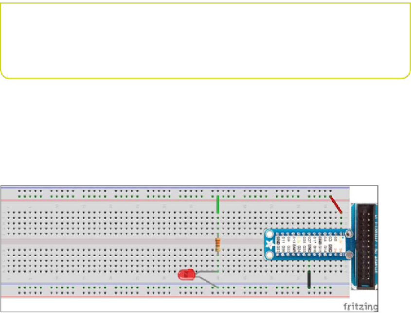
First you are going to wire up the circuit on the breadboard. Figures 5-6 and 5-7 show
a diagram of how the LED is wired to your computer.
FIGURE.5-6
An LED and a resistor wired to a Raspberry Pi
1.
Look at the LED and find the shortest wire. This is the negative side of the LED
(the cathode). Connect this to the 0V power rail at the bottom of the breadboard.
2.
The other leg of the LED will be longer, and this is the positive side (the anode). Push
one leg of the resistor into the same breadboard strip as the LED long lead and the
other leg of the resistor into a strip on the top half of the breadboard. Remember that
the resistor is needed to limit the amount of current that flows through the LED.