Biomedical Engineering Reference
In-Depth Information
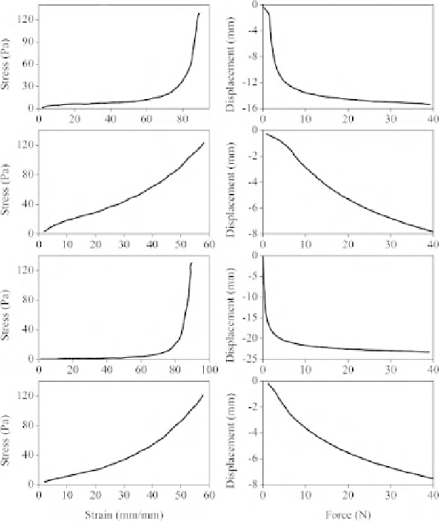
(a) A2(3/4 inch)
(b) EVA(1/2 inch)
(c) ICF400(1 inch)
(d) B1(3/4 inch)
Figure 11.8
Mechanical compression test results for four elastomeric materials, left column:
stress-strain relationship and right column: force-displacement relationship
each point of the curve. In order to accomplish this, a negative feedback closed-loop
control system with feed-forward PID controller was used, which monitored the position
of the shaft, compared its position against the desired position and prepared appropriate
commands to the actuator in order to move the shaft accordingly.
In order to design a controller for the system, first a model for the linear actuator had
to be found. Figure 11.9 shows the block diagram of the system.
For simplification, we neglected some blocks, such as the position sensor and the
analog-to-digital and digital-to-analog converters, since these are linear and operate as
simple unity gain. To find the transfer function for the linear actuator and the driver
circuit, the PID controller was replaced by a unity gain device. Figure 11.10 shows the
simplified block diagram of the linear actuator and the driver.