Biomedical Engineering Reference
In-Depth Information
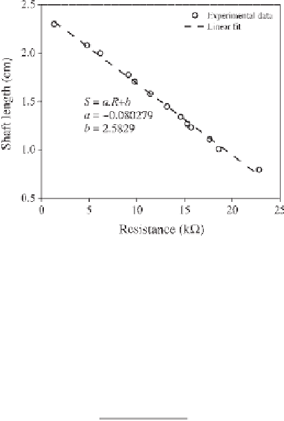
Figure 11.7
The relationship between shaft length and resistance
Using the linear relation of the shaft length and resistance, the position of the shaft
could easily be determined by measuring the resistance of the potentiometer. To measure
the resistance, a circuit, similar to that shown in Figure 11.6, was used in which the only
difference was that the FSR was replaced by a potentiometer. The relationship between
shaft length and the measured voltage
V
s
can be found in a similar way to Equation 11.3:
1
b
a
F
=
V
V
s
−
1
R.a
−
(11.4)
where
a
=
−
0.080279,
b
= 2.5829,
R
=10k
,and
V
+
=5V.
Therefore, the applied force
F
and the displacement of the shaft can be found using
Equations 11.3 and 11.4.
11.5 Stress-Strain Curves
For this study, the mechanical properties of several materials were determined using
mechanical compression tests for which the results are shown in Figure 11.8.
Each row in this figure shows an elastomeric material. The left column shows the
stress-strain curve. The right column shows the real force-displacement relation for this
same material. These force-displacement relations were used in this study to simulate
the same elastomeric behavior with the actuator.
11.6 PID Controller
To replicate the behavior of elastomers, the linear actuator must follow the
force-displacement relationship of each and, by so doing, simulate Young's modulus at