Biomedical Engineering Reference
In-Depth Information
in Figure 4.15a, when a rigid object is used as the target, no deformation occurs in the
beam. Although the PVDF films at the supports respond to the applied force, no output
from the middle PVDF film (extensional mode) is expected. However, a soft object under
aload
F
will bend the beam.
As shown in Figure 4.15b, c, larger beam deflection occurs for softer contact objects.
Therefore, the PVDF film, which is firmly adhered to the beam, elongates, and develops
a charge proportional to the bending stress which, itself, is dependent on the extent of
bending. The maximum amount of bending can be controlled at the design stage by
selecting the material of the flexible beam, as well as its thickness and length, for a
maximum given load. A beam with higher Young's modulus, or thickness, shows less
deflection, but can sustain a higher applied load. Conversely, a soft beam deflects easily
and produces a higher output charge, but it may not be a good choice for high load
applications since it cannot develop enough gripping load. Thus, with such a design, a
balance between the softness, load, and the design output charge must first be established.
For a given sensor, the thickness and material property of the beam are known, thus the
deflection of the beam will only be a function of the flexural rigidity of the contact object.
As described, the sensor consists of a top and a bottom part. The bottom part forms
the supports and is the base for the top part which consists of hanging beams. The
top part encompasses the clamped - clamped hanging beams which are used for softness
measurements. For softness sensing, the applied force, as well as the resultant deformation,
needs to be recorded. The magnitude of the applied load can be measured by piezoelectric
films that are sandwiched between the top and bottom parts. However, to measure the
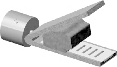
resulting deflection, PVDF films are attached to the beams. Figure 4.16 shows how this
sensor can be integrated with MIS graspers.
A sensor unit, for instance, with two or more beams can be considered as a module. In
the remainder of this chapter, to avoid unnecessary complexity, a design with three teeth,
as shown in Figure 4.17, is considered. This module can then be repeated in an array to
cover the whole length (or width) of the grasper. Figure 4.17 shows the backside view of
the top part of a sensing module with three sensing elements.
Three PVDF films working in extensional mode (
d
31
) were attached to the beams in
order to measure the deflection. Two end support PVDF films, working in the thickness
Figure 4.16
A proposed design of the smart grasper in which the incorporation of a microfabri-
cated sensor is presented (See Plate 2)