Biomedical Engineering Reference
In-Depth Information
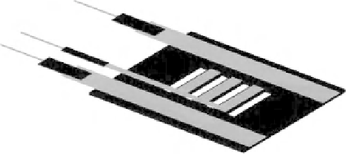
Figure 4.17
Backside view of the sensor's top part. The positions of the PVDF films and the
electrode configurations are illustrated in this view. Arrows on the PVDF film strips indicate the
orientation of the drawn direction of the PVDF film (See Plate 3)
mode (
d
33
), were sandwiched between the top and bottom parts in order to measure the
total applied load.
To ensure a firm grasp, the ideal sensor should be corrugated, which has been taken
into consideration for the current design. Depending on the application, it is possible to
have one sensorized jaw or to have both jaws sensorized. In the latter case, the capability
of the sensor for locating hidden lumps will increase. For the present study, one jaw was
considered for sensor integration.
The dimensions of the sensor, and particularly the beams, should be determined for
a given range of force and softness for any specific application. Using a number of
parameters, the desired working range or sensitivity of the sensor can be achieved. For
instance, the length, width and thickness of the beam can affect the load capacity of
the sensor as well as its sensitivity. Short and thick beams withstand higher loads, but
show less flexibility and, as a result, lower piezoelectric output would be obtained. Thin,
long beams show the opposite behavior and are appropriate for delicate applications
such as pulse detection, therefore, depending upon the application, dimensions should be
determined accordingly. Another influential factor in determining the overall dimensions
of the sensor is the dimensions of the original grasper into which the sensor is to be
integrated. The number of hanging beams, or sensing units, should also be determined in
order to satisfy the required spatial resolution.
In order to miniaturize a suitable sensor for integration with existing MIS graspers,
batch processing techniques should be utilized instead of manual techniques. For instance,
PVDF films should be deposited directly onto the target areas.
However, since at the time of prototyping, this technology was not available for micro-
fabricating the sensor, the dimensions were selected in such a way that pre-fabricated
PVDF films could be cut and placed on the designated areas. Figure 4.18 shows the
dimensions that were considered for this work. The length and width of each beam is 7
and 2 mm, respectively.
Although a sensor with these dimensions cannot be integrated into current MIS graspers,
the feasibility of sensor microfabrication, taking into account incumbent difficulties, and
sensor capabilities, were investigated in this work. To have maximum sensitivity and yet
avoid the difficulties of working with very thin silicon wafers, the thickness of silicon
used was 180 μm.