Hardware Reference
In-Depth Information
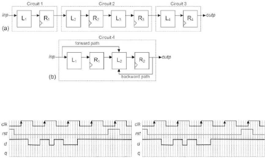
Figure 2.16
RTL pipeline (a) with loopless circuits only and (b) with a looped circuit.
Figure 2.17
On the downside, pipelining increases the latency (number of clock cycles needed
for a signal to travel though the system), which is not always acceptable. Conse-
quently, both approaches (with and without the output register) are needed, and the
choice of one or the other will be determined by the application.
The example in i gure 2.16a contains only loopless stages, but looped circuits can
also be found (generally, more difi cult to design), as in circuit 4 in i gure 2.16b. FSMs
fall in the looped category.
To conclude this section, let us look at the order (input-output latency) of the
synchronous circuits just described (i gure 2.16). Circuits 1 and 3 are order-1 synchro-
nous because the input-output transfer takes one clock cycle. Circuit 2 is order-2
synchronous because the transfer takes two clock cycles. Finally, circuit 4 is order-1
synchronous because its input affects L
2
directly, so its effect shows up at the output
after just one clock cycle (L
2
-R
2
pair).
2.7 Exercises
Exercise 2.1: DFF Response
Figure 2.17 shows waveforms for the clock, reset, and data inputs to the DFF of i gure
2.2a.