Hardware Reference
In-Depth Information
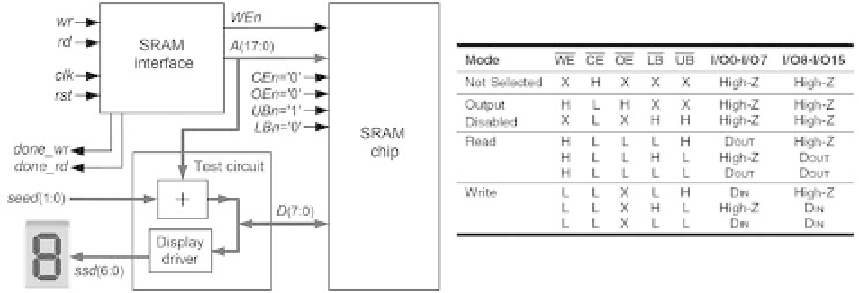
Figure 13.1
Setup for the experiments with the SRAM memory interface introduced in i gure 11.16, also
including a test circuit. The device's truth table is also shown.
The signals in lines 16-19 are for the test circuit.
seed
(line 17), set by two switches,
is added to the actual address (
A
, line 14) to produce the test data (
D
, line 16), which
is displayed on a seven-segment display by means of the signal
ssd
(line 18). Two LEDs
are lit by the signals
done_wr
and
done_rd
(line 19) to indicate when the test circuit
has i nished writing to or reading from the memory, respectively.
The second part of the code (
declarations
) is in lines 21-56. In the FSM-related
declarations (lines 24-26), the enumerated type
state
is created to represent the
machine's present and next states. In the auxiliary-register-related declarations (line
29),
A_reg
is created to deal with the auxiliary register (observe that the address is the
signal that appears in the recursive expressions, so that is the signal to be stored in
that register). In the timer-related declarations (line 32), the signals needed to build a
0.5-s timer are created, to be used in the
read1-read2
transition (see
t
=
T
2
) of i gure
11.16c, so the user has enough time to observe the value presented on the display
during the tests. Finally, a function is created in lines 35-56 to implement later the
SSD driver (integer-to-SSD conversion).
The third and i nal part of the code (
statements
) is in lines 58-149. It contains six
sections, described next.
The i rst section (lines 61-64) of the statements produces the static signals to
be connected to the SRAM chip during the tests. Note that they are all enabled
(because they are active low), except for the upper byte of the data word, which is not
used here.
The second section (lines 67-69) of the statements contains an
always_ff
block,
which implements the timer (needed in the
read1-read2
transition; the
write1-write2
transition is made at full clock speed). This code is similar to the template of section
10.2. Both timer control strategies (section 8.5) are allowed for this FSM.
The third code section (lines 73-75) is another
always_ff
block, which implements
the auxiliary register, exactly as in the template.