Hardware Reference
In-Depth Information
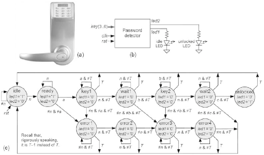
Figure 8.22
Password detector. (a) A password-protected door lock. (b) Circuit ports. (c) A Moore-type
solution.
The desired circuit features are the following (where
T
corresponds to 3 s):
a) When the system is in the
idle
state, LED
led1
(
idle
) must be on and LED
led2
(
unlocked
) must be off.
b) During the time a password is being entered both LEDs must be off.
c) If the correct password is entered,
led2
must be turned on for a time
T
, with
led1
still off, after which the system must return to
idle
(during that time interval a new
password must not be accepted).
d) If the time interval during which a key is kept pressed or between two key presses
is longer than
T
, it must be considered an error, so the machine should return to
idle
.
e) Passwords with repeated digits must be allowed.
A Moore-type solution for this problem is presented in i gure 8.22c. The three digits
that comprise the password are called
a
,
b
, and
c
;
n
means
none
, which is the character
corresponding to none of the keys pressed (“1111”—see the table in exercise 5.14).
Note that both LEDs remain off during the process. To keep the diagram as clean as
possible, a slightly simplii ed representation was used (for example, the
a
and
T
condi-
tions on the arrows mean
key
=
a
and
t
=
T
− 1, respectively). The time during which
led2
stays on is the time that the user has to open the door in a corresponding physi-
cal implementation.