Hardware Reference
In-Depth Information
Based on section 8.10, the number of l ip-l ops needed to implement this circuit is
as follows. For the state register:
M
FSM
= 11 states; therefore,
N
FSM
= 4 if sequential or
Gray encoding is used, 6 for Johnson, or 11 for one-hot. For the optional output reg-
ister: glitches are generally not a problem in this kind of application, so
N
output
= 0. For
the timer: because
t
state_max
= 3 s, and assuming
f
clk
= 50 MHz,
T
max
= 15·10
7
clock cycles
results, so
N
timer
= 28. Therefore,
N
total
= 32, 34, or 39.
The analysis of the need for reset and synchronizers is left as an exercise (exercise
8.15).
8.11.8 Triggered Circuits
This section shows FSMs for triggered circuits with both bistable and monostable
behavior. The former can hold any logic level ('0' or '1') forever, whereas the latter
(also called
one-shot
) always returns to the initial value ('0', for example) after a i nite
time interval. The input (triggering signal) is denoted by
x
, and the output (response)
is called
y
.
The input can be either synchronous (generated by a circuit operating with the
same clock as the triggered circuit) or asynchronous. However, the circuit itself is
always synchronous, so the output goes up or down only at the proper clock edge.
For example, if we say that
y
goes to '1' when
x
goes to '1', it means that
y
goes to '1'
at the i rst (positive) clock transition after
x
goes to '1'.
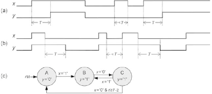
Two signals produced by bistable circuits are depicted in i gure 8.23. Note that
y
does not return to '0' (initial value) automatically. The signal in i gure 8.23a is trig-
gered by the condition “
x
= '1' during
T
clock cycles” and detriggered by
x
= '0'. The
signal in i gure 8.23b is triggered by
x
= '1' and detriggered by the condition “
x
= '0'
during
T
clock cycles.”
Figure 8.23
(a, b) Signals produced by triggered bistable circuits (note that the output does not return to zero
automatically). (c) Solution for the case in b.