Graphics Reference
In-Depth Information
Ta b l e 6 . 4
Three-dimensional reconstruction results for the raw forged iron surface of the connec-
tion rod, obtained based on comparison of the cross section shown in Fig.
6.16
a. Albedo determi-
nation marked as 'initial' denotes that the albedo was estimated prior to the iteration process either
based on specular reflections or based on depth from defocus data and was not changed afterwards,
while 'adapted' denotes an estimation of the albedo during the iteration process
Utilised information
Albedo determination
Figure
z
RMSE (
μ
m)
SfS
Equation (
5.23
), initial
6.17
281
SfPR
Equation (
5.23
), initial
6.17
56
SfS, DfD
Equation (
5.24
), initial
6.18
1153
SfPR, DfD
Equation (
5.24
), initial
6.18
55
Stereo
-
6.21
80
SfS, stereo
Equation (
5.24
), adapted
6.21
50 (163)
SfPR, stereo
Equation (
5.24
), adapted
6.21
45
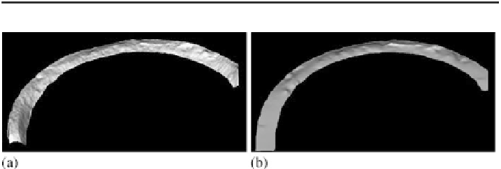
Fig. 6.22
Reconstructed surface profile of the flange. (
a
)SfPRDand(
b
) shape from shading
approach using stereo information, albedo estimated during the iteration process based on all image
pixels according to (
5.24
)
from shading and stereo approach is larger than that of the stereo reconstruction
alone, corresponding to 80
m, since no stereo data are available for the rightmost
3
.
2 mm of the cross section. Neglecting this margin yields a much smaller RMSE
of 50
μ
m. For the examined strongly specular surface, Figs.
6.20
a and
6.20
b illus-
trate that, in contrast to the shape from shading approach, the SfPR method reveals
a large amount of small scale surface detail. The results of the comparison to ground
truth data are summarised in Table
6.4
.
Figure
6.22
shows the three-dimensional reconstruction of the flange surface cal-
culated using one intensity and one polarisation angle image along with stereo depth
information. The triangulated set of stereo depth points is shown in Fig.
6.19
b. As
in the previous example, the surface albedo was estimated during the iteration pro-
cess according to (
5.24
). In contrast to the first experiment, it was not possible in
the second experiment to determine accurate ground truth values for a cross sec-
tion through the surface because the laser profilometer is not suitable for acquiring
measurements of such a large and curved surface section. Instead, we regarded the
depths of the three dents indicated in Fig.
6.19
a, for which ground truth values were
obtained by tactile measurement and compared to the reconstructed depth differ-
μ


Search WWH ::

Custom Search