Biomedical Engineering Reference
In-Depth Information
TABLE 7.3
Bonding Strength Between Calcium Phosphate Coating and Ti Substrate
Coating
Method
Thicknessof
Coating(
μ
m)
As-Coated
(MPa)
Heat-Treated
(MPa)
Immersedin
SBF(MPa)
Substrate
Reference
RF magnetron
sputtering
Mirror-polished
Ti-6Al-4V
3
60
-
45
(35)
RF magnetron
sputtering
Mirror-polished
Ti-6Al-4V
3-4
42-56
-
-
(36)
RF magnetron
sputtering
Mirror-polished
Ti-6Al-4V
3-4
27
23
-
(37)
RF magnetron
sputtering
Mirror-polished
CP Ti
0.5
60-80
-
30-60
(33)
RF magnetron
sputtering
Blasted
Ti-6Al-4V
0.5
60-80
50-60
-
(38)
IBD
Mirror-polished
Ti-6Al-4V
0.6
64.8
-
-
(12)
PLD
Mirror-polished
CP Ti
10
30-40
-
-
(18)
Plasma
spraying
Blasted
CP Ti
80-100
45
-
39.1
(60)
Plasma
spraying
Blasted
Ti-6Al-4V
200
30
-
20
(61)
Plasma
spraying
Blasted
Ti-6Al-4V
150
23
26
4.6
(62)
Plasma
spraying
Blasted
Ti-6Al-4V
50
35
-
-
(63)
Plasma
spraying
Blasted
CP Ti
135
6.7
-
-
(64)
covered with apatite with a needlelike texture after 21.6 ks.
(27)
The surface texture of the
HAp coating on which the apatite phase formed in a short period had a cauliflower-like
structure, and the formation of an apatite phase was preferential at hollow places of the
cauliflower-like texture.
(27)
Apatite formation is perhaps closely related to the elution of cal-
cium and phosphate ions from bioceramics into SBF.
(67)
The concentration of these eluted
ions increased at the hollow places in the film, which must have caused the formation of
the apatite phase in a short period by increasing the supersaturation of apatite in the solu-
tion. The spatial gap on the surface of thermally oxidized Ti substrates induced apatite
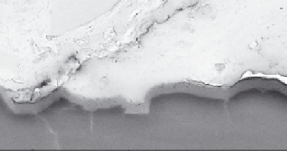
Epoxy glue
Resin
Coating
Ti-6Al-4V
5 µm
FIGURE 7.28
SEM image of cross section of OAp-coated Ti-6Al-4V plate with blasted surface after adherence test.


Search WWH ::

Custom Search