Environmental Engineering Reference
In-Depth Information
(a)
(b)
(d)
(f )
(h)
AgNW/CNT
CNT only
100
Ag
Cotton
Ws CNTs
80
60
40
20
Live cells
(c)
(e)
(g)
200 nm
0
-20
-10
0
10
20
1 mm
10 µm
Dead cells
Voltage (V)
FIGURE 12.13
Schematic, fabrication, and structure of cotton, AgNW/CNT device. (a) Schematic of proposed active mem-
brane device. (b) Treatment of cotton with CNTs. (c) Treatment of device with silver nanowires (AgNWs).
(d) Integration of treated cotton into funnel. (e) SEM image showing large-scale structure of cotton ibers.
(f) SEM image showing AgNWs. (g) SEM image showing CNTs on cotton ibers. (h) Inactivation eficiency at
ive biases for AgNW/CNT cotton as well as CNT-only cotton. (From Schoen, D.T. et al.,
Nano Lett.
, 10, 3628, 2010.
With permission.)
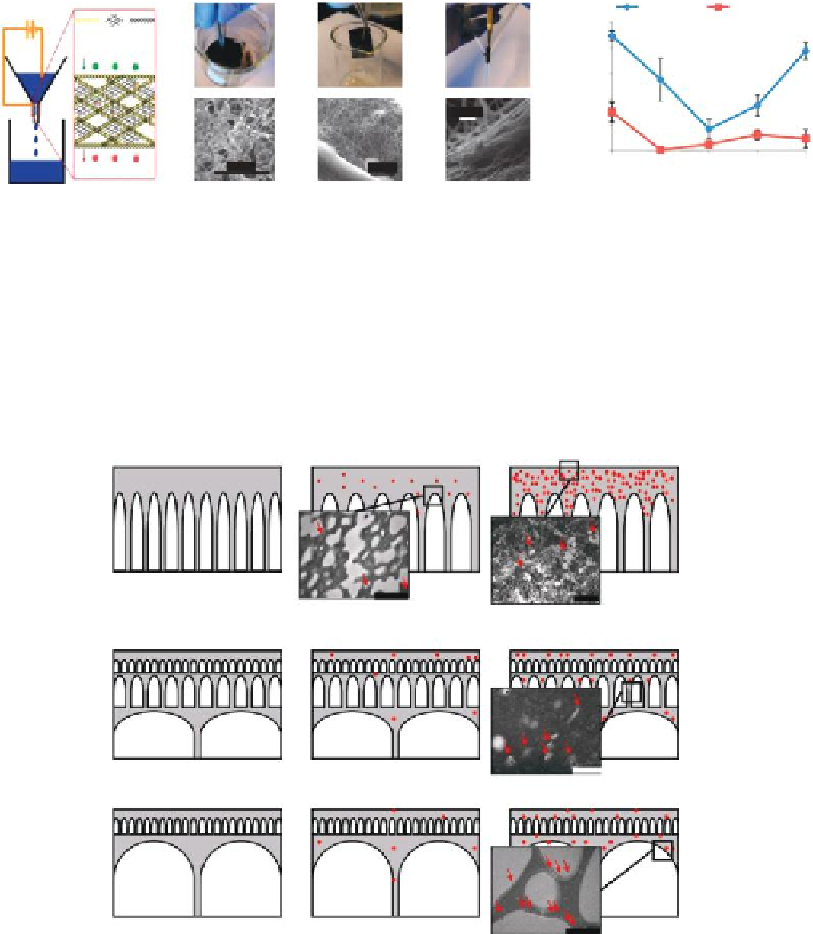
PSf/Ag
in
type I
PSf/Ag
ex
type I
PSf type I
1 µm
2 µm
PSf/Ag
in
type II
PSf/Ag
ex
type II
PSf type II
400 nm
PSf/Ag
in
type III
PSf/Ag
ex
type III
PSf type III
1 µm
FIGURE 13.1
Example of nanomaterials that could be afixed to a membrane surface. (From Figure 5.1 in Chapter 5,
Multifunctional Nanomaterial-Enabled Membranes for Water Treatment, pp. 59-75, by Tarabara, V.V. Reprinted
from
Nanotechnology Applications for Clean Water
, Diallo, M.; Duncan, J.; Savage, N.; Street, A.; Sustich, R., editors,
Elsevier Ltd., Kidlington, UK (2009). Reprinted with permission of Elsevier.)