Graphics Programs Reference
In-Depth Information
wrong direction, and rotating it is not an option at this point because this
would break the constrained geometry, you can still work around this
limitation. Drag the reference plane grip past the other end, which will flip
the orientation of the reference plane and the connector. Another option is
to use named reference planes, choose the Pick A Plane option, and select
the hosting plane from the drafting area.
Plane Direction
If you draw a reference plane from left to right in a plan view,
connectors attached to it will point up. A reference plane drawn from
right to left will cause the connectors to point down. In other words,
always draw your reference planes clockwise to ensure the proper
default location for your connectors.
ThedecisionofwhethertousetheFaceorWorkPlaneoptionforconnectors
dependsonhowyouwanttocontrolthelocationoftheconnector.Whatever
method you choose, once a connector is placed, you can adjust its properties
so that the equipment family will behave as desired in your projects.
Duct Connectors
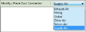
You can select the system type of a duct connector from the Options Bar,
as shown in
Figure 19.20
,
when you click the Duct Connector button on the
Create tab in the Family Editor.
Figure 19.20
Defining the system type for duct connectors
The Global option enables the air system to be based on the system the
equipment is connected to when the family is used in a project. A good use
of the Global option is for fans, where the same fan family could be used
for any system type. Fitting connectors do not have parameters to define
air system behavior, and they are typically used on duct-fitting families to
establish connectivity.