Graphics Programs Reference
In-Depth Information
3. Hover your cursor over any one of the air terminals, and press the Tab
key. This highlights the system, as indicated in
Figure 10.46
.
Left-click,
and the Modify | Duct Systems tab is activated. Click the Generate
Placeholder button.
4. Click the Settings button on the Options Bar, and check that the Duct
Conversion settings are as follows:
• Main duct: Rectangular Duct: Mitered Elbows/Tees
• Offset: 11′-0″ (3,300 mm)
• Branch duct: Rectangular Duct: Mitered Elbows/Tees
• Offset: 11′-0″ (3,300 mm)
• Flexible duct: Flex Duct Round: Flex - Round with a maximum
length of 6′-0″ (1,800 mm)
5. Use Solution Type: Network, 1 of 6, and click the Finish Layout button.
Activate the default {3D} view and notice that, as shown in
Figure 10.47
,
the main run of duct is shown as a single line. If the flexible duct is also
shown as a single line, this is not by design; it indicates that the flexible
duct is not connected correctly, which needs to be rectified.
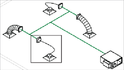
Figure10.47
Default 3D view with flex errors
6. If the flex duct is too short to be displayed properly, select one of the
rectangular-to-round transitions and move it 2′-0″ (600 mm) toward
the center of the duct run. This stretches both the placeholder duct and
the flex duct, as shown in
Figure 10.48
.
Repeat this process for each
transition. You may find it easier to tile the open view windows and
select the transition in the 3D view, but then actually move it in the plan