Graphics Programs Reference
In-Depth Information
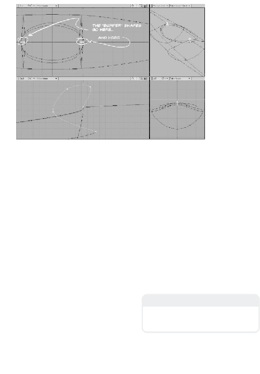
Figure 13-10
8.
Next, with the curves of the rest of
your kayak in the background as refer-
ence, create a little shape that will be
the profile of the rubberized bumper
that rings the opening of the kayak. It
should lie along Z=0 and be mirrored
across X=0, as shown in Figure 13-10.
When you've got these doodads done,
cut and paste them onto the layer with
the rest of your kayak, and weld their
endpoints to the ends of the top seams
and to the ends of the curves we cre-
ated in Step 7.
10. Select the curves that enclose the top
front of our kayak's spline cage in the
order shown in Figure 13-11. (The rest
of the kayak is hidden to keep screen
clutter to a minimum as we work.) In
the Make Spline Patch window, set Per-
pendicular to
5
segments distributed
WRT (with respect to)
Length
, and set
Parallel to
10
segments distributed
WRT
Knots
. You should get a patch
that looks like the one shown in Figure
13-11. (When you select the curves in
this clockwise order, you'll have to flip
your polys in order to get their normals
facing the right way.)
9.
Double-check to make sure that all
your curves' endpoints are welded
and/or merged to their neighbors'
endpoints.
Note
Now that you've got the “spline cage” built,
we can patch it to create geometry we can
render in Layout.
Using the Perspective viewport's ability to
orbit your model is a great help in selecting
elements within a complex object.