Civil Engineering Reference
In-Depth Information
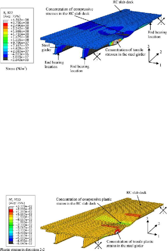
Figure 7.19 Stress (principal
in direction 2-2) contours at failure of the composite
bridge (enlarged 10 times).
midspan did not reach the concrete compressive strength. In
Figure 7.19
,
the
stress (principal stresses in direction 2-2) contours at failure of the composite
bridge are plotted. It can be seen that the yield stresses were not reached at
midspan in the concrete (compressive stresses with negative sign) and the
yield stresses were reached in the lower steel beam flanges (tensile stresses
with positive sign). In addition, in
Figure 7.20
, the plastic strain (principal
strains in direction 2-2) contours at failure of the composite bridge are plot-
ted. It can be seen that the plastic strains were concentrated at midspan the
lower steel beam flange (tensile strains with positive sign). Furthermore, in
Figure 7.21
, the von Mises yield stress contours at failure of the composite
bridge are plotted. It can be seen that the yield stresses were reached at
Figure 7.20 Plastic strain (principal in direction 2-2) contours at failure of the composite
bridge (enlarged 10 times).
Search WWH ::

Custom Search