Civil Engineering Reference
In-Depth Information
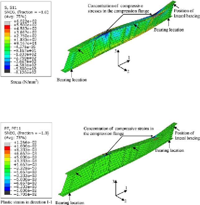
Figure 6.21 Stress (principal in direction 1-1) contours at failure of the full-scale built-up
I-section plate girder T3.
Figure 6.22 Plastic strain (principal in direction 1-1) contours at failure of the full-scale
built-up I-section plate girder T3.
489.3 kN at a deflection of 40.6 mm, while the ultimate failure load pre-
dicted from the finite element analysis was 490.3 kN at a deflection of
44 mm. The finite element failure load was 0.2% higher than that observed
in the test.
6.6 FINITE ELEMENT MODELING AND RESULTS
OF EXAMPLE 4
In this example, we can use the finite element modeling approach adopted
for the simulation of plate girders T1, T2, and T3 to model a full-scale
Search WWH ::

Custom Search