Civil Engineering Reference
In-Depth Information
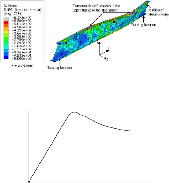
Figure 6.23 Stress (von Mises) contours at failure of the full-scale built-up I-section plate
girder T3.
500
400
300
200
100
Test
FE
0
0
20
40
60
80
100
120
Deflection (mm)
Figure 6.24 Comparison of load-midspan deflection relationships obtained
experimentally and numerically for the full-scale plate girder T3.
double-track open-timber floor plate girder railway steel bridge. The SS
double-track bridge is similar to that presented in
Chapter 1
(see
Figure 1.20) having a length of 30 m between supports and an overall length
of 31 m. The bridge was designed by the author in
Chapter 4
(see
Section 4.2) adopting the design rules specified in EC3 [1.27]. In
Figure 6.25
,
the general layout of the bridge and the bridge components comprising
main plate girders, cross girders, stringers, bracing members, stiffeners,


Search WWH ::

Custom Search