Civil Engineering Reference
In-Depth Information
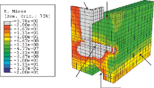
Steel beam
Reinforcement bar
Concrete
Headed stud
Profiled steel sheeting
Figure 5.36 Stress contours at failure for pushout specimen tested in [2.58, 2.59] and
modeled in [2.71].
the concrete are in the regions around the stud forming a conical shape. This
conical failure mode of concrete was explained in detail both experimentally
and numerically by Ellobody [2.68-2.70] for the investigation of pushout
tests with solid slabs and precast hollow-core slabs. The conical concrete fail-
ure is also known as concrete pullout failure since the tensile force acting on
the stud forces the slab to move up and leave a cone of concrete around the
stud. The concrete conical failure (or concrete pullout) was also observed
experimentally and discussed theoretically in the previous studies on pushout
tests with profiled steel sheeting conducted in [2.57-2.59]. The concrete
conical failure occurred, and the stud reached its yield stress near the collar.
Figure 5.37
showed the deformed shape obtained from the finite element
analysis for the 13
65 mm headed stud shear connector tested in [2.58,
2.59] and modeled in [2.71]. The verified finite element models [2.71] were
used to performextensive parametric studies. The finite element strengthswere
compared with design strengths calculated using current codes of practice.
The aforementioned finite element modeling of shear connection can
provide a good insight into the local behavior of headed shear studs in the
connection. However, to model a full-scale composite girder having many
shear studs, we can benefit now from the special-purpose elements pro-
videdinABAQUS[1.29]elementlibrary.Theshearconnectorscanbe
modeled using a nonlinear spring element (using SPRING option). The
spring element is of zero length that bears only shear force and obeys
the load-slip characteristic of the shear connector used. The positions of
Search WWH ::

Custom Search