Civil Engineering Reference
In-Depth Information
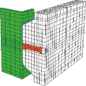
Steel beam
Headed stud
Concrete
Profiled steel sheeting
Reinforcement bar
Figure 5.37 Deformed shape at failure for pushout specimen tested in [2.58, 2.59]
and modeled in [2.71].
the spring elements coincide with the positions of the shear connectors
used in the composite beam. Because the load-slip characteristic of the
shear connector is nonlinear, the force is assumed to be a function of rel-
ative displacement in the spring and is defined by giving a table of force
values in ascending values of relative displacement. The load-slip charac-
teristic of the shear connector is obtained from the corresponding finite
element modeling of the local shear connection. It should be noted that,
for a given composite beam, loading, and design method, complete shear
interaction is defined as the least number of the connectors such that the
bending resistance of the beam would not be increased if more connectors
were provided. Partial shear interaction is assumed when the number of
connectors used in the composite beam is less than the number of shear
connectors that cause full shear interaction. In the design with complete
shear connection, it is normally assumed that the failure of shear con-
nectors does not occur and the influence of connector deformation on
the structural behavior was neglected. With partial shear connection,
the ultimate resistance of the beam depends on the ultimate resistance
of the shear connector and its ductility. In these cases, it is important
to use the correct load-slip behavior of the connector since it can cause
significant redistribution of stresses between the connectors in both
serviceability and ultimate limit states.


Search WWH ::

Custom Search