Civil Engineering Reference
In-Depth Information
that the connection deformability affected the evaluation of the effective
width of steel-solid slab composite beams. A displacement-based finite ele-
ment model for the analysis of steel-solid slab composite girders with flexible
inally developed by improving the two-node 1D displacement-based finite
element. The research is still in press and the authors suggested that the
model might be used in the accurate simulation of the behavior of composite
girders.
experimental testing of composite steel-prestressed hollow core concrete
slab girders. In the model, the concrete slab was modeled by using 2D
eight-node plane stress elements, while the steel beamwas modeled by using
2D four-node plane stress elements.
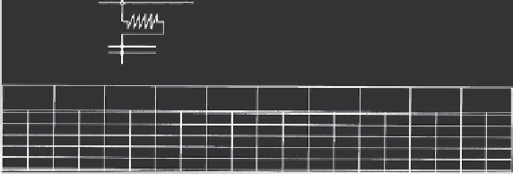
Figure 2.26
shows the finite element
eled as a separate element due to the limitation of the 2D element used, but
its effect was taken indirectly into account in simulating the shear connec-
tion behavior. Both the precast hollow core concrete slab and
in situ
con-
crete were modeled as a single concrete element that had a breadth equal
to the thickness of the prestressed hollow core concrete units and with com-
bined material properties. The shear connectors were modeled by using
spring elements that obeyed the load-slip characteristic of the shear stud con-
cast hollow core beam was modeled in a simplified way, the results obtained
from the model showed good agreement with the experimental results. The
model was used in carrying out parametric studies that took into account the
different parameters affecting the behavior of steel-prestressed hollow core
C. L.
1350
Interface
element
Eight-node element
Concrete Slab
150
357
Four-node element
Steel beam
150
2850
150
Knife edge support


Search WWH ::

Custom Search