Civil Engineering Reference
In-Depth Information
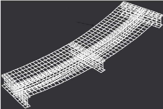
Concrete slab
Secondary beam
Main girder
element mesh with 1257 elements used by the authors in the analysis. The-
model. In the model, the concrete slab was simulated by four-node isopara-
metric thick shell elements with the coupling of bending stiffness, while the
steel flanges and web were modeled by four-node isoparametric thin ele-
ments with the coupling of bending and stiffness. The shear connectors
between concrete slab and steel flange were modeled by rigid beam ele-
ments. Rigid connection beam elements were used to model the shear studs
based on the assumption that no slip occurs between the concrete slab and
the steel girder. The material nonlinearities of the steel beam and the con-
crete slab were accounted in the analysis. The authors found good agreement
between experimental and numerical results in most of the cases. The
observed discrepancies in some of the results between the values predicted
numerically and that predicted experimentally are attributed to neglecting
the slip at the steel-concrete interface by using rigid elements to represent
the studs. Amadio and Fragiacomo [
2.85
] used the finite element method
to model steel-solid slab composite girders. The model was used in studying
the evaluation of effective width for serviceability and ultimate analysis.
In the model, the shell elements were used in modeling both the steel beam
and the concrete slab. A nonlinear elastic law represented the behavior of the
shear connection. The effects of steel and concrete material nonlinearities
were taken into consideration. Although this research was applied on can-
tilever beams, the authors concluded that the numerical study demonstrated


Search WWH ::

Custom Search