Information Technology Reference
In-Depth Information
clock cycles to complete their work, and the correct output first appears during clock
cycle #12. More generally, the time to complete signal distribution will be 4N - 2
clock cycles, where N is the number of inputs. This relationship is valid for all values
of N C 2, including the devices shown in Fig.
4
(N = 2) and Fig.
9
(N = 3). It has
also been shown to hold for a device with N = 4[
16
].
The device shown in Fig.
9
was simulated for all eight possible combinations of
the three inputs, and it yielded the correct outputs for each of the eight cases.
4
Sequential Signal Distribution Network
The SDN structure shown in the previous section is optimized for use with combi-
national logic devices. The signal distribution requirements for a sequential device
have particular characteristics that require modifications to this design in order to
optimize the complete system.
It is possible, as shown in Fig.
12
, to consider a sequential device to be composed
of two combinational devices (a next state decoder and an output decoder), along with
a number of D flip-flops to store the current state of the system. In this case, each of
the two combinational devices could be implemented using an SDN followed by the
necessary combinational logic gates. The problem comes in the region between
the next state decoder and the output decoder, which requires a large number of wire
crossings in order to route the four bits of the current state back to the input of the next
state decoder.
These wire crossings can be eliminated by using a modified SDN to route the
current state signals back to the input of the next state decoder, as shown in Fig.
13
.
Not only does this modified SDN eliminate the need for wire crossings between the
two decoders, it also fills the role of the SDN for the next state decoder. As shown in
Fig.
13
, the outputs of the next state decoder (the current state of the device) all leave
the next state decoder in the same clock phase, and these horizontal lines (labeled
S0-S3) are available to be applied to the output decoder, if one is required. In addi-
tion, they are also routed vertically through a series of one-cell regions that propagate
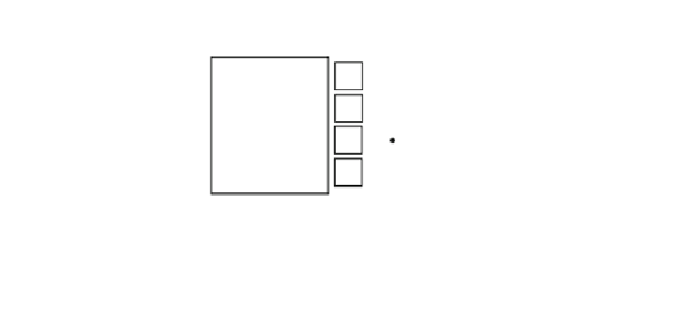
D
D
D
D
Next State Decoder
Output Decoder
Fig. 12. Schematic representation of a sequential logic device implemented using two
combinational devices (a next state decoder and an output decoder) as well as four (in this case)
D flip-flops to store the current state of the device. Note the large number of wire crossings
between the next state decoder and the output decoder.


Search WWH ::

Custom Search