Graphics Reference
In-Depth Information
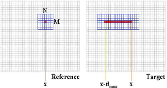
Fig. 5.6
Support windows, of size
M
×
N
, for cost aggregation in local algorithms at disparity
d
.
In the reference image, the support window is centered on point (
x
), while in the target image, the
support windows are centered on points [
x
,
x
−
d
max
]
5.5.1 Local Algorithms
Local algorithms process each point independently ignoring relationship between
neighboring disparity values. For this reason, they do not enforce an explicit smooth-
ness constraint on the target disparity map, and typically for each disparity candidate
within the disparity range
D
, compute the matching cost by aggregating neighbor-
ing pixels (often on rectangular patches referred to as
support
windows, as depicted
in Fig.
5.6
). Cost aggregation is often explicitly obtained by summing up, accord-
ing to different strategies, each pointwise matching cost within the support window,
as depicted in Fig.
5.6
. However, it is worth noting that some recent approaches
implicitly aggregate costs in constant time, independently of the size of the support
[
7
,
27
].
More generally, cost aggregation performed by most local algorithms can be fig-
ured out, as depicted in Fig.
5.7
, as a filtering [
15
] of the DSI data structure according
to different strategies. Examples of filtering operations applied to the DSI are aver-
aging/sum, bilateral filtering [
46
], approximated bilateral filtering [
19
], guided filter
[
12
], etc. Since local algorithms completely ignore relationships between neighbor-
ing points and different disparity values within the disparity range, from the com-
putational point of view, this means that
D
filtering operations can be applied in
parallel to the DSI in order to aggregate matching cost for each disparity candidate.
Adopting for the processing pipeline the same clock of imaging sensors, the com-
putation of the
D
filtering operations for each point should hopefully finish within a
single (pixel) clock cycle. This fact potentially enables a high degree of parallelism
(multiplied by a factor
D
compared to the sequential case) but at the same time it
imposes that all the data required in the DSI (highlighted in the DSI depicted in
Fig.
5.7
), or a subset of this data centered in the point under examination, must be
accessed in parallel. Therefore, at least the portion of data highlighted in Fig.
5.7
should be carefully managed, by means of appropriate data structures and buffering