Graphics Reference
In-Depth Information
(b)
(a)
obstacle
OCCLUDED
COLLISION
object surface
SAFE
viewing
direction
Safe
OUTSIDE
Collision
Occlusion
Outside
camera center
camera
origin
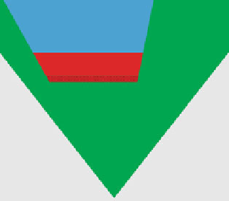
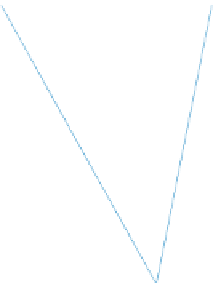
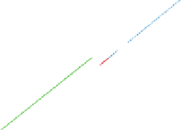
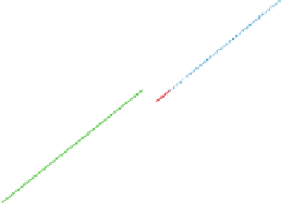
Fig. 4.10
Collision checking logic:
a
trajectory segments inside the viewing volume of the camera
are classified as: SAFE if unobstructed (
green
), COLLISION if directly behind an object surface
(
red
), and OCCLUDED if behind on object;
b
test trajectories in a simulation: collision checking
result for a set of nine
horizontal
trajectories
cle dynamics quickly results in undesirable trajectories. Third, the dynamics become
highly nonlinear especially when performing aggressive maneuvers. To address these
challenges, we deploy a motion planning approach that incorporates vehicle dynam-
ics by forward-simulating vehicle responses to waypoint control inputs, which effec-
tively reduces the planning space to only 3D.
We extended an approach that was previously used for autonomous urban driving
[
31
] to 6DOF motion with agile vehicle dynamics.
Our planner deploys a closed-loop RRT approach (CL-RRT) to grow a tree of
waypoint inputs that are used in a feedback loop to estimate flight trajectories
using a low-level controller and the quadrotor model described by How et al. [
22
].
The low-level controller consists of two layers: a linear
feedback controller
and
a
waypoint tracker
.The
waypoint tracker
keeps track of which waypoint to visit
next, and when to switch to the next waypoint segment (Fig.
4.11
). It also com-
putes the reference position/velocity and the position/velocity tracking errors. Given
these tracking errors, the
feedback controller
computes the vehicle inputs
u
collective
,
u
roll
,
u
pitch
, and
u
yaw
to maneuver the vehicle along the trajectory using regular PID
controllers for each channel.
The output of the control loop are the predicted vehicle states which define
trajectory segments that are used for collision checking. Note, that the planner simul-
taneously grows a tree of controller inputs (straight lines connecting the controller
input of a selected node to a sample, which forms an input to the forward simulation)
and a tree of collision-free dynamically feasible trajectories (output of the forward
simulation) as illustrated in Fig.
4.12
.