Environmental Engineering Reference
In-Depth Information
Table 12
The performances in the large-scale device fabricated by the lamination process
Jsc (A/cm
2
)
Rs (X cm
2
)
p(X cm
2
)
Voc (V)
FF (%)
PCE (%)
Non
3.62
0.73
37.59
0.99
93.26
516.62
100 C, 5 min
6.58
0.71
44.94
1.50
34.53
506.63
100 C, 10 min
7.04
0.69
46.71
2.27
21.59
371.70
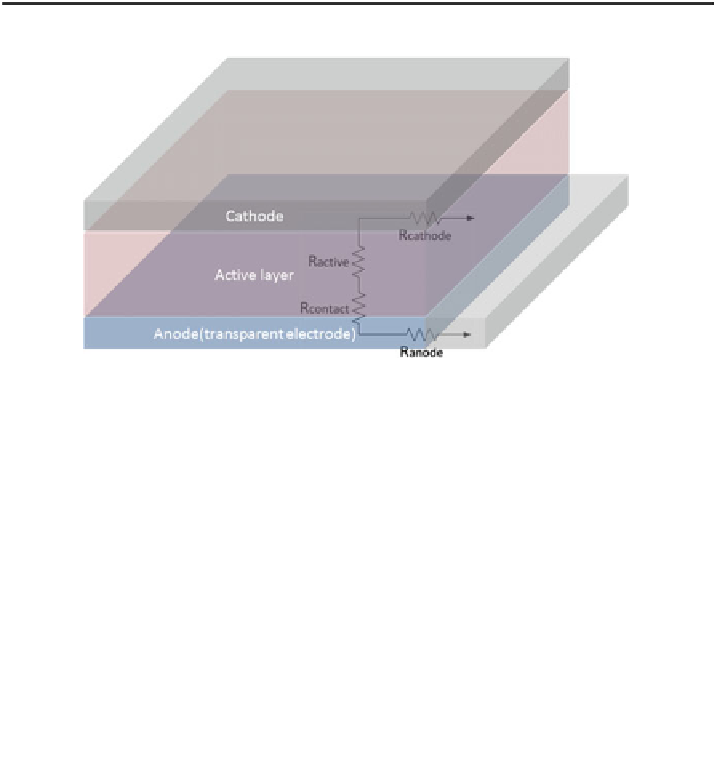
Fig. 29
Description of series resistance components inside conventional OPV cells
electrode. R
active
and R
contacts
does not increase with area scaling since they are
vertical components in the cell which have the same carrier travel distance
regardless of cell area. Furthermore, the metal cathode has negligible series
resistance compared to transparent anode electrode such as ITO, with typical
conductivity ratio of *100:1 [
18
]. Therefore, the main factor that determines the
resistive loss with increasing device size is the resistance of transparent electrode.
Figure
29
shows each component inside the cell graphically.
The effect of the series resistance can be studied in more detail with the non-
ideal equivalent circuit model, which is widely acceptable for both inorganic solar
cells and organic solar cells [
19
]. With the parasitic resistances included, the diode
equation becomes
þ
V
J
ðÞ
R
S
A
R
sh
A
ð
Þ
qV
J
ðÞ
R
S
A
J
ðÞ
¼J
0
e
1
J
ph
;
ð
17
Þ
nkT
where J
0
is the reverse saturation current, V is the applied voltage, J is the current
density of the cell, n is the diode ideality factor, k is Boltzmann's constant, T is
temperature, R
S
is series resistance, R
sh
is shunt resistance and J
ph
is the photo-
current generated by the cell. The parameters J
0
, n, R
S
, R
sh,
and J
ph
can be obtained
by fitting the diode model to the experimental J-V data from actual OPV devices
under illuminated and dark conditions. Servaites et al. [
20
] showed the impact of
R
S
on the performance of large area P3HT:PCBM BHJ OPVs using ITO anode.

Search WWH ::

Custom Search