Environmental Engineering Reference
In-Depth Information
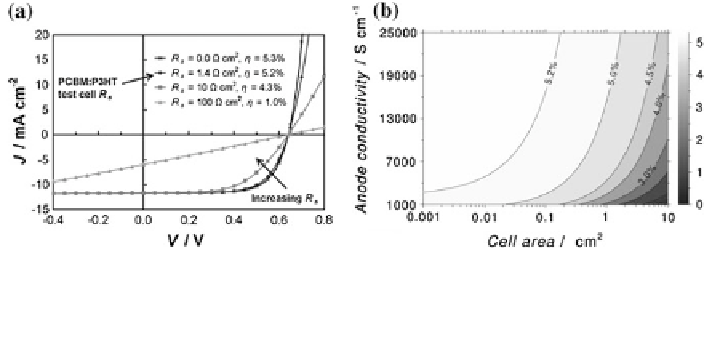
Fig. 30 a The effect of R
S
variation on projected J-V characteristics for the P3HT:PCBM test
cell. b The effect of anode conductivity and cell area on cell power conversion efficiency for the
P3HT:PCBM test cell. Reproduced from [
20
] with permission of Wiley-VCH Verlag GmbH &
Co. KGaA 2010
Figure
30
shows the effect of R
S
variation on the J-V curves for the P3HT:PCBM
test cell. In the graph, R
S
is the only parameter that changes and all the other
parameters in Eq. (
16
) are kept constant. The results show that the resistive losses
due to R
S
remain negligible with cell areas under *0.1 cm
2
. However, as cell area
increases over 0.2 cm
2
, the efficiency starts to drop significantly due to steep
increase of anode series resistance. Figure
30
b shows the relationship between
anode conductivity and cell area on power conversion efficiency of the
P3HT:PCBM device, illustrating the importance of the anode conductivity as the
cell size increases.
2.5.7 Design Strategy of Transparent Electrode for Low Series
Resistance
To reduce the series resistance of the transparent electrode of the large area OPVs,
metal grid patterns can be added to the anode side to reduce the resistive loss.
Deliberate design of electrode geometry is imperative. Several strategies have
been employed to reduce the negative effect of the series resistance on OPVs
including bus bar design [
17
], ring type design [
21
], stripe type design [
22
], and
deep trench type metal grating design with conductive polymer [
23
]. Stripe design
of the large area OPVs is the most popular type due to its simplicity and adapt-
ability to roll-to-roll process. The resistive losses from relatively high resistance of
the transparent electrode can be minimized by reducing the travel distance of the
photo-generated charges at the transparent electrode. The simplest way to achieve
this is by putting at least one side of metal lines as close as possible to the regions
of photocurrent generation. In other words, the width of the PV cell stripe should
be kept narrow with the contacts put on the long sides while the length of the stripe
does not matter as long as each layer of the solar cell device has no defects or
discontinuities. The effects of the width of the stripe in organic solar cells were
Search WWH ::

Custom Search