Environmental Engineering Reference
In-Depth Information
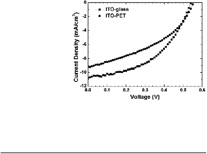
Fig. 28 The device
performance of the laminated
devices using ITO-glass and
ITO-PET
Table 11
The device performances fabricated by the lamination process
Jsc (mA/cm
2
)
Device
Voc (V)
FF (%)
PCE (%)
ITO-PET
9.21
0.56
40.95
2.11
ITO-glass
10.87
0.55
46.1
2.76
2.5.6 Influence of Series Resistance in Large Area Solar Cells
We have already seen the impact of series resistance in large area device to the
achievable OPV efficiency. Practical large area solar cell devices suffer more from
resistive losses, which should be minimized to maintain the performance of the
devices. We will quantify the effect of series resistance, R
S
by computing the
resistive power loss. In small area devices, organic semiconducting active layers
contribute more to the resistive power loss than other factors. However, as the size of
the devices increases, the R
S
of the transparent electrodes become the main factor of
the resistive loss [
17
]. The total resistive power loss per unit area is given by
Þ
2
P
R
¼
R
S
J
max
A
ð
¼ R
S
AJ
max
;
ð
15
Þ
A
where P
R
is the total resistive power loss per unit area, R
S
is the series resistance in
the device, J
max
the current density, and A the area of the devices. R
S
in organic
solar cell contains the resistances of the anode, active layer, contacts, and cathode:
R
S
¼
R
anode
þ
R
active
þ
R
contacts
þ
R
cathode
;
ð
16
Þ
where R
active
and R
contacts
are the series resistances of active layer and contacts of
each layer, respectively. When we assume the conventional structure of organic
solar cell, cathode side is the reflective metal and the anode side is the transparent

Search WWH ::

Custom Search