Environmental Engineering Reference
In-Depth Information
(a)
(b)
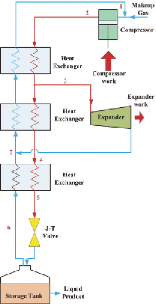
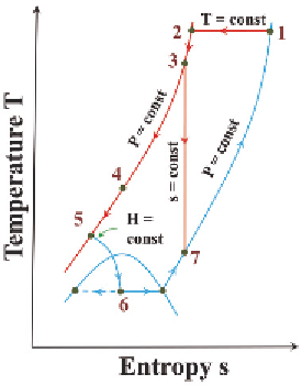
FIGURE 5.9
Schematic and temperature-entropy diagram of a simple Claude cycle. Reproduced with
permission from Barron [11]. (See color insert.)
thermal convection, and thermal conduction have to be taken into account in
designing the vessels (Fig. 5.10). The inner vessel is insulated with a multi-
layered material with spacers acting as thermal barriers. The spacers are
coated with high reflective Ag films to minimize thermal radiation loss. This
inner vessel is mounted within the outer vessel by means of specially designed
internal fixtures. The volume between the inner and outer vessels is evacu-
ated to high vacuum to avoid possible heat leaks by thermal convection. In
spite of the insulation, due to the unavoidable heat input, hydrogen will
evaporate in the tank, which will cause the pressure rise in the vessel. Pres-
sure build-up can be treated to be linearly proportional to storage time. Once
the pressure reaches the maximum operation pressure of the tank, a blow-off
valve has to be opened to release the hydrogen in order to maintain the safety
of the system. The unexpected heat input could come externally or internally.
As discussed in Chapter 1, hydrogen has two forms, the parahydrogen and
orthohydrogen. These two forms of hydrogen not only have different internal
Search WWH ::

Custom Search