Biomedical Engineering Reference
In-Depth Information
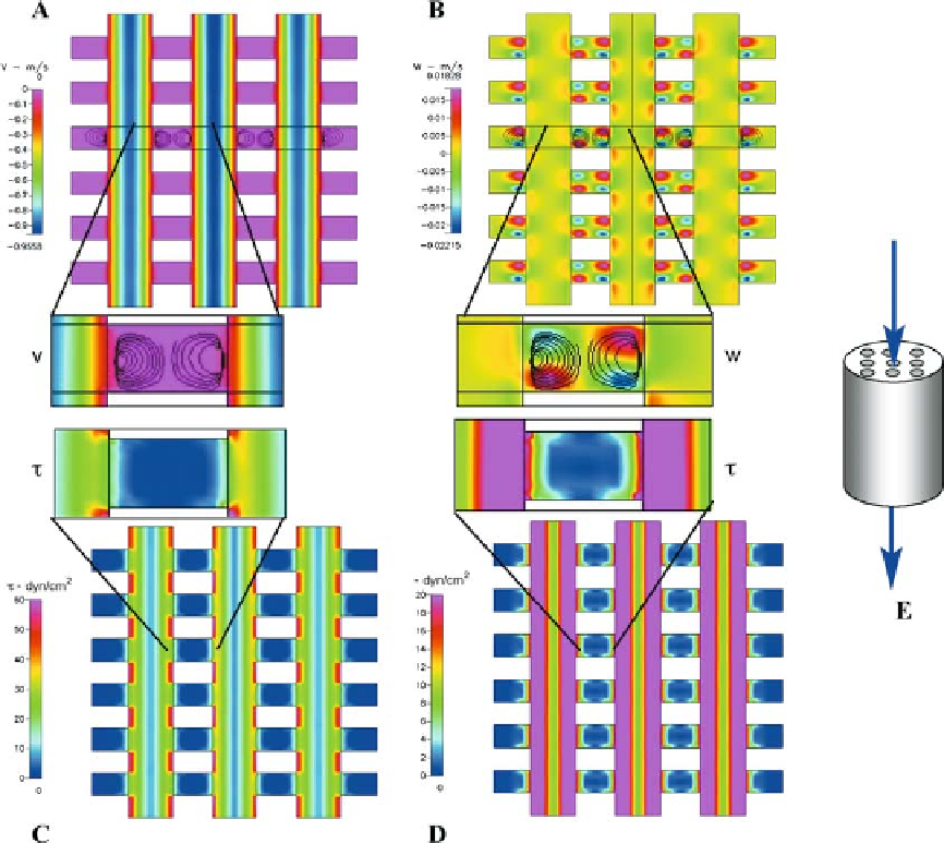
Figure 10.14.
Predictive computational model of flow through a tissue-engineering scaffold. (A) Flow (v) in longitudinal direc-
tion with close-up of streamlines in inset. (B) Flow (w) in transverse direction, with close-up in inset. (C and D) Shear stresses (t)
in the same area of the scaffold. (E) Schematic diagram showing flow direction through the cylindrical scaffold, whereby the sides
of the cylinder are sealed. Adapted from [2].
differ markedly between the through-channels
and the transverse layers as well (Fig.
trast, the low-velocity transverse layers provide
low-level shear stresses that promote cell adhe-
sion, as well as mechanical stimuli conducive
to osteoblastic differentiation.
C
and D). Wall shear stress is calculated from the
laminar viscosity and the wall strain rate,
determined through the solutions of Navier-
Stokes equations within the scaffold
τ γ
10
.
14
10.11 Epilogue
=
w
where
τ
is the shear stress at the wall,
µ
is the
We have addressed the two goals of the
chapter:
• Describing the strengths of computational
modeling approaches, when used in tandem
with experimental approaches, to unravel the
fl uid viscosity, and
is the strain rate deter-
mined from the second invariant of the stress
tensor. The high-fl ow environment of the
through-channels produces high shearing
stresses along the longitudinal walls. In con-
γ